
Method of forming a sealed channel of a microfluidic reactor and a microfluidic reactor comprising such channel

A technology for sealing channels and reactors, applied in the direction of microstructure technology, microstructure devices, manufacturing microstructure devices, etc., can solve the problems of uneven channel walls, time-consuming, complicated disassembly, etc.

Inactive Publication Date: 2009-02-04
THALES NANOTECHNOLOGIAI RT (HU)
View PDF2 Cites 2 Cited by
  • Summary
  • Abstract
  • Description
  • Claims
  • Application Information

AI Technical Summary

Problems solved by technology

These assembly processes are expensive, time-consuming and require the use of auxiliary equipment (e.g. furnaces, welding equipment) on the one hand and very advanced manufacturing techniques on the other
Furthermore, most of these reactors cannot be disassembled without being damaged, or are very complicated to disassemble if the channels need to be cleaned
[0006] Additionally, channel walls formed by the above methods without additional surface treatment are microscopically uneven (i.e., "finely textured / grained"), which will result in a relatively large surface
Consequently, the channel walls are subjected to attack by violently acting reactants, such as ozone, or, in special cases, the structure of the walls can lead to an uncontrolled decomposition of any reaction intermediates or even the reactants (ozone) themselves

Method used


Image

  • Method of forming a sealed channel of a microfluidic reactor and a microfluidic reactor comprising such channel
  • Method of forming a sealed channel of a microfluidic reactor and a microfluidic reactor comprising such channel
  • Method of forming a sealed channel of a microfluidic reactor and a microfluidic reactor comprising such channel

Examples


Embodiment Construction

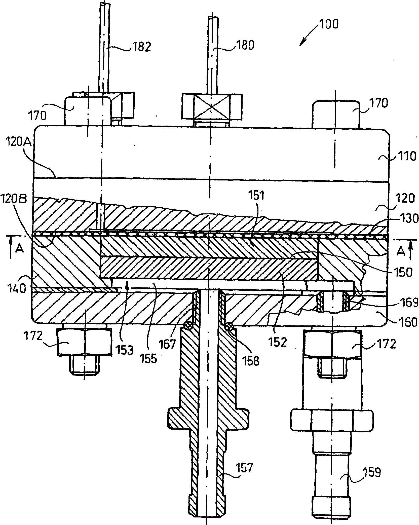
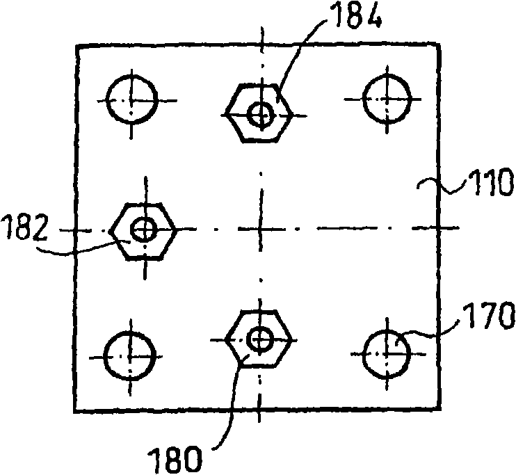
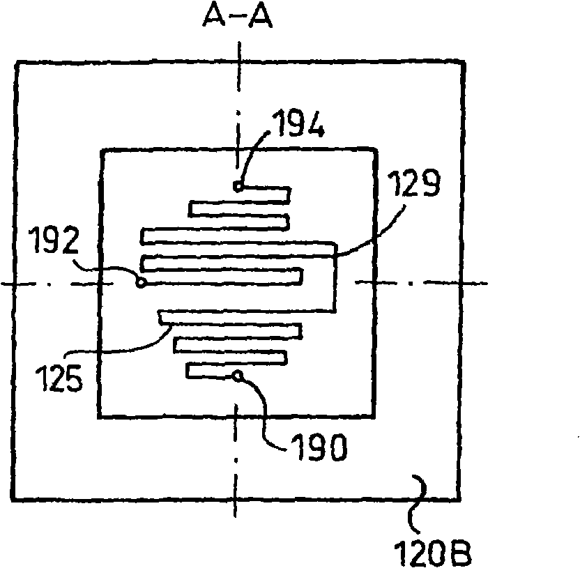
[0021] figure 1 Shown is a microfluidic reactor 100 comprising a reactor module 120 defined by a first face 120A and a second face 120B, a first confinement 110 in contact with the first face 120A of the reactor module 120, covering the reaction The closure 130 on the second face 120B of the device module 120 , the support 140 in contact with the closure 130 along its periphery, and the second limiter 160 abutting against the face of the support 140 opposite to the closure 130 . The closure member 130, the support member 140 and the restriction member 160 together define a cooling cavity 153 therebetween. A temperature control unit 150 in contact with the enclosure 130 is installed in the cooling cavity 153 . The temperature control unit 150 is securely mounted in place by the support 140 . In this arrangement, the temperature control unit 150 is separated from the second restriction member 160 by a gap, that is, the temperature control unit 150 and the second restriction me...


PUM

PropertyMeasurementUnit
Thicknessaaaaaaaaaa

Abstract

In a method according to the invention for forming a sealed channel (125) in the surface of a sheet made of a material with certain extent of plasticity, the machining surface of a tool with a rolling machining surface is brought into contact with a first point of the channel (125) to be formed in the surface of the sheet constituting a reactor block. Next, said machining surface is pressed onto the surface of the sheet with a compressive force (F) required to achieve the depth of the channel (125) to be formed, whereby the plastic material is squeezed out and becomes raised from the sheet surface on the peripheries of the depression being formed. After this, while maintaining the compressive force (F), by displacing said machining surface along the centerline of the channel (125) over the sheet surface it is rolled from the first point of the channel (125) to be formed to a second point thereof, whereby the channel (125) is machined in the material of the sheet and sealing edges (127) are created on the peripheries of the channel (125) from the material squeezed out and become raised. After creating said sealing edges (127), a closing member bearing against the sealing edges (127) is arranged at the surface of the sheet provided with the channel (125) and the sealing edges (127), and then said closing member is pressed onto the sheet by a compressive force required to deform said sealing edges (127) and is fixed in the position obtained, whereby a sealed channel (125) running between the first and second points is formed within the reactor block.

Description

technical field [0001] The present invention relates to a method of forming a sealed channel on the surface of a sheet made of a material having a certain degree of plasticity, said sheet forming a reactor module for a microfluidic reactor. The present invention also relates to a microfluidic reactor, which includes a sealed channel with an outlet and an inlet for providing a chemical reaction space, and the outlet and the inlet are both communicated with the external environment of the reactor, wherein the reactor also includes a The coupling mechanism holds and clamps together the first and second confinement members, the closure member and a cooling chamber in communication with the environment external to the reactor, said cooling chamber having a temperature control unit therein. Background technique [0002] In the chemical industry, larger sized reactors are used to carry out different kinds of chemical reactions on an industrial scale. However, flasks of much smalle...

Claims


Application Information

Patent Timeline
IPC IPC(8): B81C1/00
CPCB81C1/0046
Inventor D·绍洛伊N·沃尔高F·邦茨F·达尔瓦T·卡拉纳茨奇L·格德尔哈叙
Owner THALES NANOTECHNOLOGIAI RT (HU)
Learn More