
Cooling method and device of bellow forming module

A cooling device and cooling method technology, applied to corrugated products, tubular items, other household appliances, etc., can solve the problems of leakage of cooling liquid, low cooling efficiency, intermittent injection of cooling liquid, etc., and achieve strong vacuum suction, Improved reliability and lower operating costs

Active Publication Date: 2009-02-11
潍坊中云科研有限公司
View PDF0 Cites 2 Cited by
  • Summary
  • Abstract
  • Description
  • Claims
  • Application Information

AI Technical Summary

Problems solved by technology

However, the current water-cooling scheme for corrugated forming modules either has the disadvantages of complex structure and high failure rate, resulting in frequent leakage of coolant, or has the disadvantage of being too simple in structure and low in cooling efficiency, making high-speed production impossible
[0004] For example: the water cooling method of Unocal Company in Germany is to install a quick automatic plug-in opening and closing joint on the top of the module. The joint is pulled out, retracted, inserted, forward and reciprocating with the operation of the module, and the coolant is injected into the module at the forward section of the joint. Internal pipeline, the disadvantage of this method is that the coolant is injected intermittently, the cooling of the module is insufficient, and the structure is complicated. The joints are frequently inserted and pulled up and down, which makes the seal wear quickly and cause leakage.
[0005] Moreover, the cooling of all bellows forming modules in the prior art is to add high-pressure coolant at the liquid inlet of the module. Due to the existence of the pipeline conversion device and the liquid resistance of the mold cooling cavity, the cooling of the coolant will inevitably occur. Leakage, the liquid outlet of the module also has the same coolant leakage problem, the leakage problem has seriously affected the quality and production efficiency of the product, and caused pollution to the environment
[0006] How to prevent leakage and improve cooling efficiency has become a worldwide problem in this technical field, and so far, international well-known companies have not made breakthroughs

Method used


Image

  • Cooling method and device of bellow forming module
  • Cooling method and device of bellow forming module
  • Cooling method and device of bellow forming module

Examples


Embodiment Construction

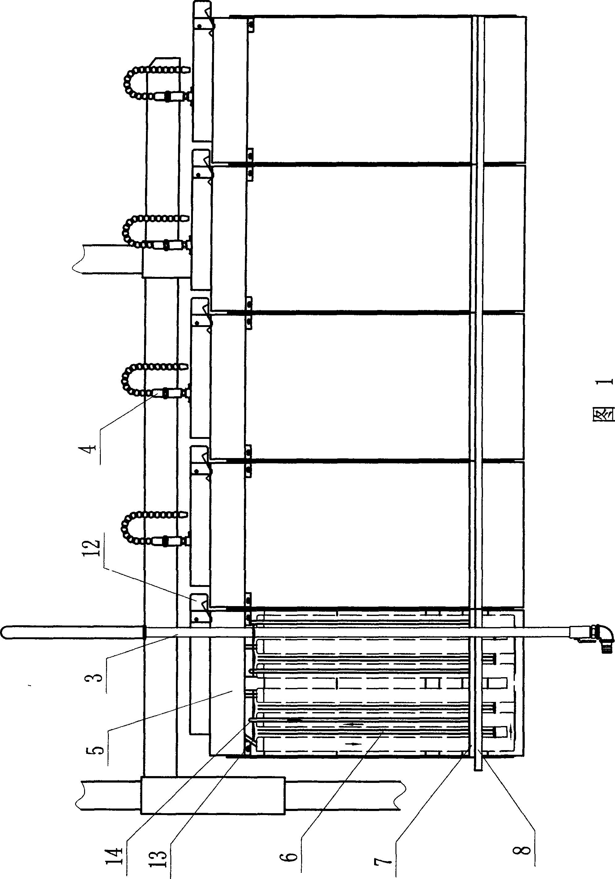
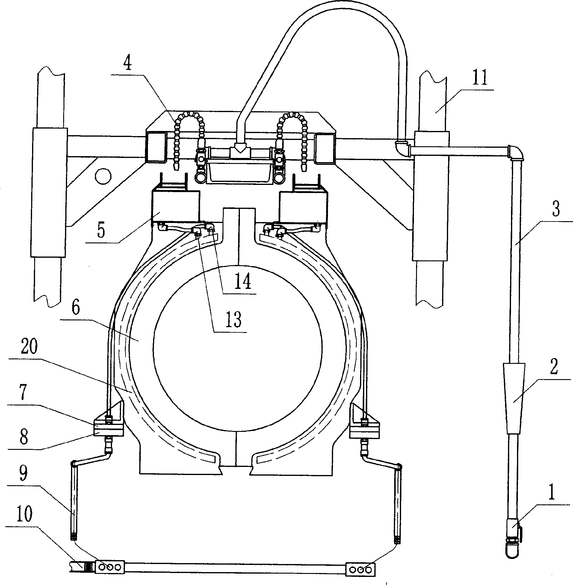
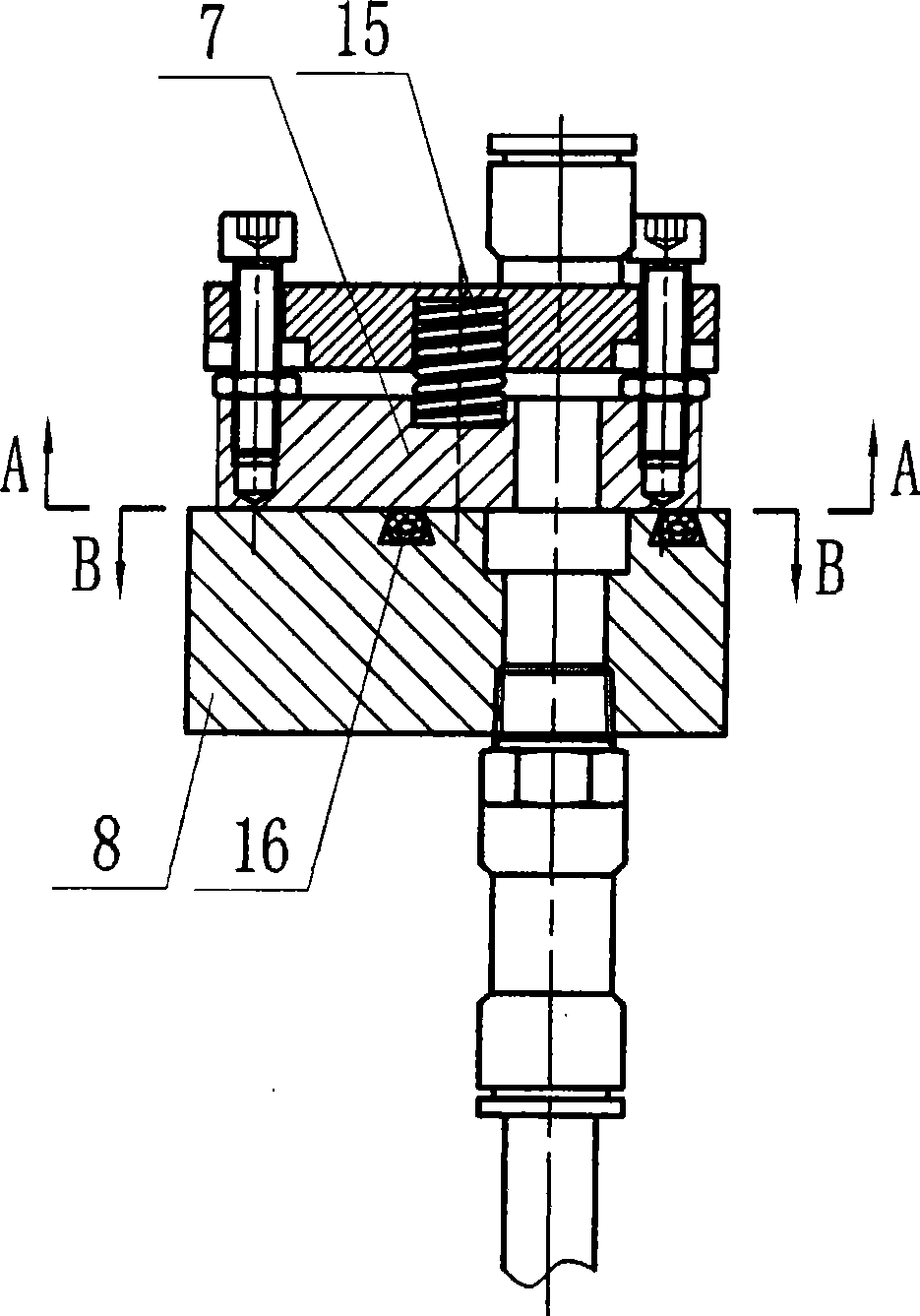
[0031] The method for cooling a corrugated pipe forming module includes sequentially performing a cooling liquid supply step, a module cooling step, and a cooling liquid return step, wherein: the cooling liquid supply step includes a pressure-free liquid inlet step at the cooling liquid inlet, and the cooling liquid of the module is The steps include the step of circulating cooling in the inner cavity of the module, and the step of liquid return of the cooling liquid includes the step of vacuum negative pressure liquid return at the outlet of the cooling liquid.

[0032] The non-pressure inlet step of the coolant inlet is to install a coolant liquid storage device connected to the coolant inlet on the corrugated forming module body, and the coolant liquid storage device is a liquid containing device arranged on the upper body of the forming module groove or fixedly installed on the top of the forming module independent liquid tank, using the weight of the cooling liquid and vac...


PUM


Abstract

The invention discloses a cooling method and a cooling device for a corrugated pipe forming module. A cooling liquid storage device is arranged on the corrugated pipe forming module so as to ensure continuous and pressureless liquid inlet for a cooling liquid inlet opening, pipeline transfer is eliminated, the structure is simple, and the leakage phenomenon caused by the pipeline transfer is avoided; a cooling liquid return device adopts a vacuum suction pipe so as to ensure that a cooling liquid outlet opening realizes vacuum negative liquid return, the cooling liquid leakage is not caused even if a small amount of air leaks at the liquid outlet opening, the vacuum suction force is stronger, the flow volume of the cooling liquid to pass through the module cooling chamber is larger, and the cooling effect is better.

Description

technical field [0001] The invention relates to the technical field of manufacturing plastic corrugated pipes, in particular to a cooling method for a molding module, and also to a cooling device for the molding module using the method. Background technique [0002] The process of manufacturing plastic bellows is: the plastic raw material is first heated by the plastic extruder to be plasticized, and then transformed into a molten state. The molten plastic material passes through the extrusion die to form a tube blank in the shape of a tube, and the tube blank enters the After forming the mold, it is formed into a plastic corrugated pipe product, and after effective cooling, the high temperature plastic corrugated pipe whose shape and size have not been determined is cooled and shaped, so that the plastic corrugated pipe product has a specific shape and size that can be maintained. This process That is, the cooling and sizing of plastic bellows. Moreover, the cooling effici...

Claims


Application Information

Patent Timeline
IPC IPC(8): B29C47/86B29L16/00B29L23/00
Inventor 张泽奎韩炳强王培森
Owner 潍坊中云科研有限公司
Learn More