Profile control agent of injection well

A profile control agent and injection well technology, which is applied to drilling compositions, chemical instruments and methods, etc., can solve the problems of reduced injection volume and injection ratio of the target layer, high initial viscosity, and small profile control radius, etc. Increased heterogeneity or coefficient of variation, improved shelf life and effectiveness, increased relative permeability

Active Publication Date: 2009-02-11
DAQING OILFIELD CO LTD +1
View PDF0 Cites 13 Cited by
  • Summary
  • Abstract
  • Description
  • Claims
  • Application Information

AI Technical Summary

Problems solved by technology

It is one of the important measures to control intra-layer and inter-layer contradictions in oilfields. However, the profile control agents currently used have the following problems: due to the high initial viscosity, the profile control agent enters the non-profile control target layer, and then pollutes the non-plugging parts. ; Due to the large amount of profile control agent entering the target layer, the injection rate and injection ratio of the target layer are reduced, the radius

Method used


Image

  • Profile control agent of injection well
  • Profile control agent of injection well
  • Profile control agent of injection well

Examples


Embodiment 1

[0013] Embodiment 1, prolongation and control experiment of profile control agent gelation time:

[0014] Under indoor static conditions, control the concentration of 0.05-0.4% of the performance regulator to adjust the gelation time, and the corresponding relationship is shown in Table 1 below.

[0015] Components of profile control agents with different gluing time Table 1

[0016] Polyacrylamide Concentration A(%)

[0017] As can be seen from Table 1, the gelling time can reach up to 60 days.

Embodiment 2

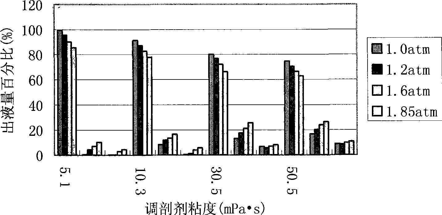
[0018] Example 2. Experiment of profile control agent diversion performance under different viscosity and different injection pressure conditions of the same model:

[0019] Adopt 2052, 514, 106×10 -3 μm 2 The cores were connected in parallel, and the proportion of profile control agent entering the core was measured under different viscosity and different injection pressure conditions. The results are shown in Table 3 and figure 1 . See Table 2 for the preparation of profile control agents with different viscosities

[0020] Preparation of profile control agents with different viscosities Table 2

[0021] profile control agent viscosity

(mPa·s) polyacrylamide

Concentration A(%) polyacrylamide

Subquantity (millions) Chromium salt crosslinking agent dichromic acid

Sodium concentration B(%) performance modifier thiourea

Concentration C (%) 5.1 0.5 150 0.5 0.4 10.3 0.5 180 0.5 0.4 30.5 0.5 420 0.5 0.4 50.5 0.5 600 ...

Embodiment 3

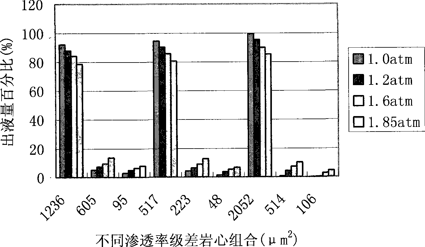
[0025] Example 3. Different model systems with the same viscosity and different injection pressures for profile control agent diversion performance experiment: Three sets of parallel cores were used in the experiment, and the permeability gradients were 2, 2.5, and 4 respectively.

[0026] When the viscosity is 5.1 mPa s, the proportion of profile control agent entering the core under different injection pressures is shown in Table 4

[0027]

[0028] It can be seen from the experimental results that the higher the injection pressure, the greater the viscosity of the profile control agent, and the smaller the proportion of the profile control agent entering the high permeability layer. Therefore, reducing the injection pressure and reducing the viscosity of the profile control agent can effectively increase the proportion of the profile control agent entering the high permeability layer. The larger the permeability difference, the larger the proportion of profile control ag...


PUM

PropertyMeasurementUnit
Viscosityaaaaaaaaaa
Average permeabilityaaaaaaaaaa

Abstract

The invention relates to an injection well profile modification agent which comprises polyacrylamide with the molecular weight of 1-2 million, hydrolysis degree less than 5% and consistency of 0.5%, inorganic chromium salt cementing agent sodium dichromate with the consistency of 0.15-0.5%, thiocarbamide with the consistency of 0.05-0.4% and residual quantity of water. After the profile modification agent is adopted, the permeability of high permeability layer reaches 40-60% and proportion of the profile modification agent entering the destination layer can be improved from 70% to more than 95%.

Description

Technical field: [0001] The invention relates to a profile control agent used in the field of oil field chemistry, in particular to a profile control agent for injection wells. Background technique: [0002] Profile control is to inject profile control agent into the high-permeability layer (segment) in the oil layer to reduce the water absorption (fluid production) capacity of the high-permeability layer, so as to achieve the purpose of balancing the injection (production) profile. It is one of the important measures to control the conflicts within and between layers in the oilfield, but the profile control agent currently used has the following problems: due to the high initial viscosity, the profile control agent enters the non-profile control target layer, and then pollutes the non-plugging part ; Due to the large amount of profile control agent entering the target layer, the injection rate and injection ratio of the target layer are reduced, the radius of profile contro...

Claims


Application Information

Patent Timeline
IPC IPC(8): C09K8/512
Inventor 王德民王研赵嵩刘建宇
Owner DAQING OILFIELD CO LTD
Why Eureka
Try Eureka