

Placement head comprising a readjusting mechanism, and placement robot
An assembly head and gripping device technology, which is applied to electrical components, electrical components, etc., can solve the problems that the restoring force cannot be predetermined, the placing force cannot be predetermined, and the assembly process is adversely affected, so as to achieve weight and cost advantages, structure The effect of compactness and improved dynamics
- Summary
- Abstract
- Description
- Claims
- Application Information
AI Technical Summary
Problems solved by technology
Method used
Image

Examples
Embodiment Construction
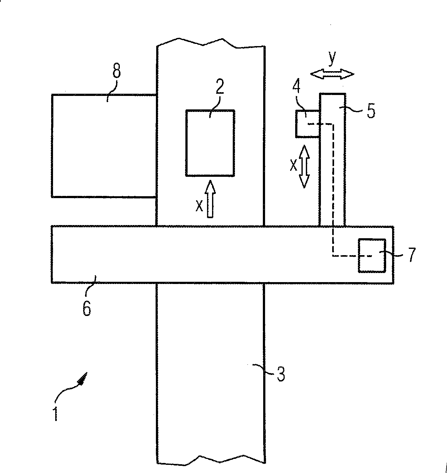
[0027] figure 1 Shown is an automatic assembly machine 1 for equipping substrates with electrical components. The substrate 2 to be assembled is transported by a conveying line 3 (for example a conveyor belt) to an assembly station, where it is equipped with electrical components, and then transported away from the assembly station. The assembly process is carried out by the assembly head 4 . The assembly head 4 is mounted on a positioning arm 5 and is movable on the positioning arm 5 in a direction (arrow x) parallel to the conveying direction (arrow x) of the substrate 2 . The positioning arm 5 is itself mounted on a support 6 straddling the conveying line 3 and is movable on the support 6 in a direction (arrow y) perpendicular to the conveying direction. The automatic assembly machine 1 also includes a control device 7 coupled with the positioning arm 5 and the assembly head 4 for controlling the moving process. A feeding device 8 is provided in the feeding area next to ...
PUM
 Abstract
Description
Claims
Application Information