Round steel end chamfering machine

A technology of chamfering machine and round steel, which is applied in the direction of metal extrusion dies, etc., to achieve the effect of simple setting structure, safe operation and simple structure

Inactive Publication Date: 2010-06-30
河南六建建筑集团有限公司
View PDF0 Cites 4 Cited by
  • Summary
  • Abstract
  • Description
  • Claims
  • Application Information

AI Technical Summary

Problems solved by technology

The disadvantage of using lathes to process such workpieces is that it cannot meet the urgent needs of mass production in construction projects, and when there are no lathes around the construction site, the supply of a small number of parts becomes very difficult
The construction site is generally equipped with a steel bar cutting machine and threading machine, but after cutting the workpiece with the cutting machine, due to local deformation at the end, it cannot be used directly on the threading machine, and can only be used after chamfering
At present, there is no round steel end chamfering equipment on the market that can use cutting machines and threading machines to make double-ended screws on site

Method used


Image

  • Round steel end chamfering machine
  • Round steel end chamfering machine
  • Round steel end chamfering machine

Examples


Embodiment Construction

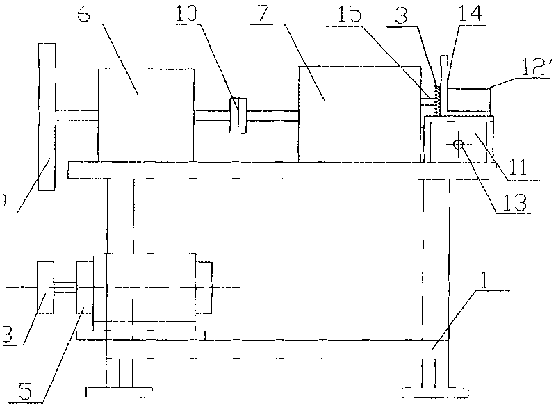
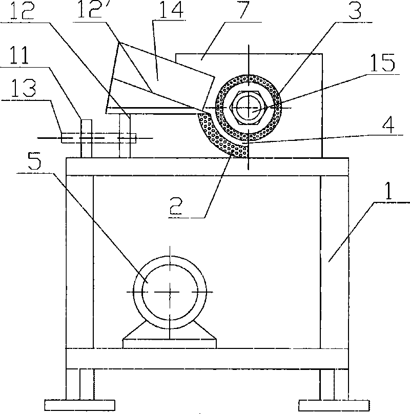
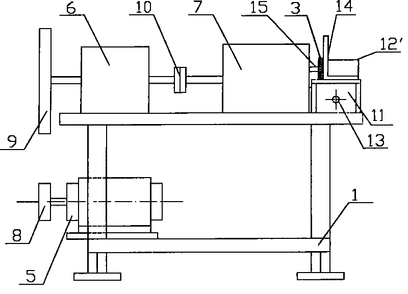
[0016] Such as figure 1 and figure 2 As shown, the round steel end chamfering machine of the present invention comprises a frame 1, and a power unit and a mold group are arranged on the frame 1, and the mold group includes a flower tooth arc mold 2 and a flower tooth tapered mold 3 arranged concentrically, The smaller end diameter of the flower tooth cone mold 3 faces the outside of the frame, and the round steel processing channel 4 is formed between the flower tooth cone mold 3 and the flower tooth arc mold 2, and the power unit communicates with the flower tooth cone mold 3 through the transmission device. Drive connection. Described power unit is electric motor 5, and described transmission device comprises reduction box 6 and transmission case 7; The output shaft of described motor 5 is provided with small belt pulley 8, and the input shaft of described reduction box 6 is provided with large belt pulley 9. The small pulley 8 and the large pulley 9 are connected by bel...


PUM


Abstract

The invention discloses a chamfering machine for the end tip of round steel. The chamfering machine comprises a stander; a power device and a mould set are arranged on the stander; the mould set comprises a flower tooth circular arc mould and a flower tooth tapered mould which are concentrically arranged; one end of the flower tooth tapered mould with small-diameter end face faces toward the outside of the stander; a round steel machining passage is formed between the flower tooth tapered mould and the flower tooth circular arc mould; and the power device is in transmission connection with the flower tooth tapered mould by a transmission device. The chamfering machine has a simple structure and convenient use and can carry out end correction and chamfering to a cut round steel workpiece in a construction field.

Description

technical field [0001] The invention relates to a round steel end chamfering machine. Background technique [0002] With the increase of high-rise buildings, a large number of double-ended screws with different specifications and a length of 0.5m to 2.0m will be used to fix the formwork in the formwork project. This kind of screw is used in a large amount during construction, and it is worn out quickly, and it is often faced with the situation of urgent need for processing and production. Since this kind of screw is a non-standard part and has different specifications, it was processed by lathe in the past. The disadvantage of using lathes to process such workpieces is that it cannot meet the urgent needs of mass production in construction projects, and when there are no lathes around the construction site, the supply of a small number of parts becomes very difficult. The construction site is generally equipped with a steel bar cutting machine and threading machine, but a...

Claims


Application Information

Patent Timeline
Patent Type & Authority Patents(China)
IPC IPC(8): B21C23/02B21C25/02
Inventor 张进崔峰巅郎义勇康卫良陆臻瑜杨广军王冠杰金跃山
Owner 河南六建建筑集团有限公司
Why Eureka
Try Eureka