Self-melting and welding method for hydraulic oil tube

A technology of hydraulic oil pipe and welding method, applied in welding equipment, welding equipment, auxiliary welding equipment, etc., can solve the problems that welding reliability cannot be kept stable, products are prone to blow holes, undercuts, and operators have high technical level requirements. The effect of reducing technical level requirements, reducing air holes, and improving the working environment

Inactive Publication Date: 2009-02-18
WUHU SHUANGYI HYDRAULIC COMPONENT
View PDF0 Cites 10 Cited by
  • Summary
  • Abstract
  • Description
  • Claims
  • Application Information

AI Technical Summary

Problems solved by technology

[0002] When the hydraulic oil pipes used in the hydraulic system are produced, the steel pipes and pipe joints are usually combined into one by welding, whether it is manual arc welding, CO 2 Welding and gas welding belong to the filler-type traditional process welding, which requires high technical level of the operator, and the product is prone to defects such as pores and undercuts. Especially small and medium-sized thin-walled hydraulic oil pipes are easy to weld through, and the welding reliability cannot be kept stable.

Method used


Image

  • Self-melting and welding method for hydraulic oil tube
  • Self-melting and welding method for hydraulic oil tube

Examples


Embodiment Construction

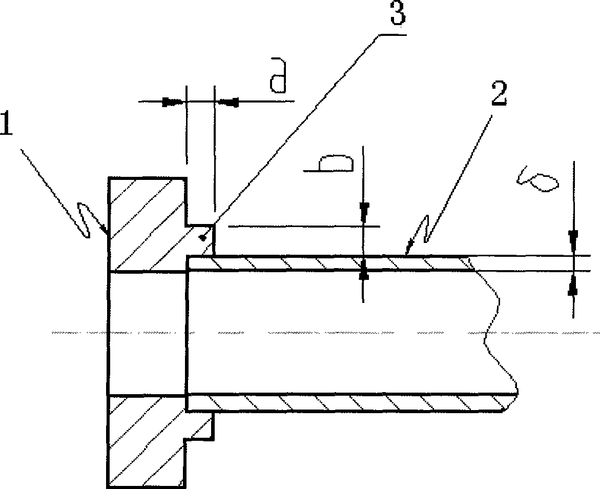
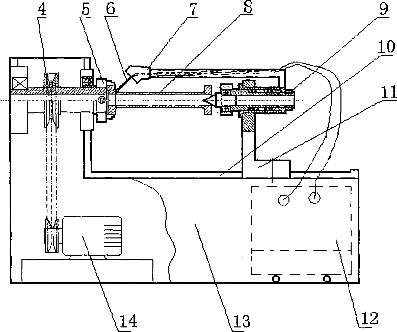
[0016] Such as figure 1 As shown, a hydraulic oil pipe argon tungsten arc welding self-fluxing welding equipment includes a body 2, argon tungsten arc welding welding machine 1, a motor 3, a transmission mechanism 4, a clamping mechanism 5, a welding torch fixing frame 7, a welding torch 6, and a thimble Tailstock 9 and control mechanism (not shown in the figure), argon tungsten arc welding machine 1, motor 3 and transmission mechanism 4 are placed in the cavity of body 2, and body 2 side upper part has horizontal rail 10, and thimble tail The tailstock base 11 at the bottom of the frame 9 can reciprocate along the horizontal rail 10. One end of the welding torch holder 7 is affixed to the upper part of the outer side of the thimble tailstock 9. The welding torch 6 is installed on the welding torch holder 7. The upper part of the body 2 has a positioning The clamping mechanism 5 of the pipe joint of the hydraulic oil pipe workpiece 8. When welding, the pipe joint of the hydra...


PUM


Abstract

The invention discloses a self-fusion welding method for a hydraulic oil pipe, which comprises the following steps: 1) a pipe joint of the hydraulic oil pipe is matched with a steel pipe, and 2) welding equipment is adopted to weld the pipe joint of the hydraulic oil pipe and the steel pipe into a whole. The pipe joint of the hydraulic oil pipe consists of a pipe joint body and a self-fusion lug boss axially extending at one end of the pipe joint body; and a circular welding seam can be formed at the joint of the pipe joint and the steel pipe after the welding fusion of the self-fusion lug boss is solidified. With the mode adopted, the self-fusion welding method for the hydraulic oil pipe greatly reduces defects such as air holes during the welding, improves the qualification rate of welding products, reduces the technical class requirement on operating personnel, can guarantee the stability and consistency of the welding quality to middle and small thin-wall hydraulic oil pipes, increases work efficiency, and improves the work environment of welding fields.

Description

technical field [0001] The invention relates to a method for making a hydraulic oil pipe, in particular to a method for self-melting welding of a hydraulic oil pipe. Background technique [0002] When the hydraulic oil pipes used in the hydraulic system are produced, the steel pipes and pipe joints are usually combined into one by welding, whether it is manual arc welding, CO 2 Welding and gas welding are both filler-type traditional process welding, which requires high technical level of the operator, and the product is prone to defects such as pores and undercuts. Especially small and medium-sized thin-walled hydraulic oil pipes are easy to be welded through, and the welding reliability cannot be maintained stably. Contents of the invention [0003] The technical problem to be solved by the present invention is: to provide a hydraulic oil pipe self-melting welding method, the hydraulic oil pipe self-melting welding method can improve the qualified rate of welding product...

Claims


Application Information

Patent Timeline
Patent Type & Authority Applications(China)
IPC IPC(8): B23K9/16B23K9/28B23K37/053B23K101/06
Inventor 王四牛
Owner WUHU SHUANGYI HYDRAULIC COMPONENT
Why Eureka
Try Eureka