Repeatable locking device

A technology of repeated locking and locking cylinders, which is applied in the direction of the deceleration device of the AC motor, the guide device of the aerospace vehicle, the magnetic object, etc., and can solve the problems of needing an air source, poor reliability, and high quality, and achieve less moving parts and less The effect of small mass and simple structure

Inactive Publication Date: 2012-05-23
BEIHANG UNIV
View PDF0 Cites 0 Cited by
  • Summary
  • Abstract
  • Description
  • Claims
  • Application Information

AI Technical Summary

Problems solved by technology

The locking device based on carbon fiber composite material and aviation steel wire rope is unlocked by pyrotechnics. Its main disadvantage is that it can only be used once. The impact of pyrotechnics on the structure is large during work, and harmful gases are generated when the gunpowder burns or explodes.
Although the pneumatic locking device can be used repeatedly, its structure is more complicated, and it needs an air source, its reliability is poor, and its quality and volume are large
The stepper motor + gear transmission pair + nut and screw transmission pair locking device can also be reused, but the structure is complex and there are many moving parts, so the quality is relatively high and the reliability is poor

Method used


Image

  • Repeatable locking device
  • Repeatable locking device
  • Repeatable locking device

Examples


Embodiment Construction

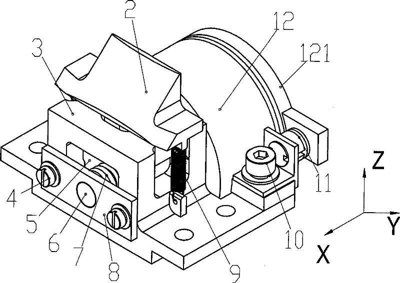
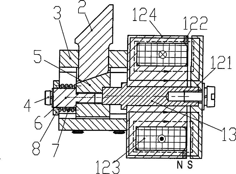
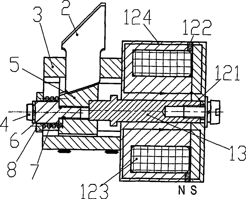
[0020] like figure 1 , figure 2 , image 3 , Figure 4 , Figure 5 and Image 6 Shown, the present invention is made up of electromagnet 12, lock column 2, support 3, pillar 5, spring column 6, compression spring 7, baffle plate 8, extension spring 9, sensor 11, electromagnet 12, sensor 11 and baffle plate 8 is fixed on the bracket by the fastening screw 4 and the connecting screw 10, and a gap of 0.5-2 mm is formed between the suction cup 121 and the magnetic pole of the electromagnet 12, and the support 5 and the suction cup 121 can only move in the horizontal x-axis direction in the bracket 3, such as figure 1 As shown in the x-axis direction in , when locking is required, current is applied to the coil 123 so that the direction of the magnetic field generated by the current is the same as the direction of the magnetic field generated by the permanent magnet 122, as shown in figure 2 As shown by the solid line and the dotted line, the suction cup 121 overcomes the sp...


PUM


Abstract

A repeated locking device can be used as a protective device of a magnetic suspension flywheel, mainly consisting of an electromagnet, a locking pillar, a support, a supporting pillar, a spring pillar, a compression spring, a connection shaft, a baffle, a stretching spring and a sensor; the electromagnet, the sensor and the baffle are fixed on the support through a tightening bolt and a connection bolt; a magnet seat is fixed on one end of the support through the connection bolt, an adhesive disc is arranged on the outer side of the electromagnet and is connected with the supporting pillar; the locking pillar is connected with the support through the stretching spring; the spring pillar is arranged between the baffle and the supporting pillar and is connected with the supporting pillar; the compression spring is arranged on the outer side of the spring pillar and is connected with the baffle through the spring pillar; the sensor and the baffle are fixed on the support through the tightening bolt and the connection bolt; the locking pillar is arranged on the upper side of the supporting pillar. The locking device protects the magnetic suspension flywheel system, and has the advantages of repeated utilization, high reliability, simple structure, and the like.

Description

technical field [0001] The invention relates to a magnetic levitation flywheel locking device, in particular to a reusable, high reliability, low power consumption and simple structure magnetic levitation flywheel locking device, which can be used as a protection device for a magnetic levitation flywheel system. Background technique [0002] The magnetic levitation flywheel is a long-life, high-precision spacecraft attitude control actuator. The spacecraft will generate severe vibration and shock during launch. Since the magnetic levitation flywheel adopts magnetic bearing technology, there is a gap between the stator and the rotor. If no protective measures are taken, the magnetic levitation flywheel system will be damaged, so a locking device is required; In addition, when the magnetic levitation flywheel needs to work normally, the locking device of the magnetic levitation flywheel must be unlocked so that the magnetic levitation flywheel system enters a normal working st...

Claims


Application Information

Patent Timeline
Patent Type & Authority Patents(China)
IPC IPC(8): H02P3/26H01F7/122B64G1/24
Inventor 韩邦成房建成刘强王曦孙津济
Owner BEIHANG UNIV
Why Eureka
Try Eureka