LED lamp

A technology of light-emitting diodes and lamps, which is applied to semiconductor devices, light sources, electric light sources, etc. of light-emitting elements, can solve the problems of life reduction and light brightness attenuation, and achieve the effect of not being damaged.

Inactive Publication Date: 2009-02-18
CHANG WAH ELECTROMATERIALS INC
View PDF0 Cites 55 Cited by
  • Summary
  • Abstract
  • Description
  • Claims
  • Application Information

AI Technical Summary

Problems solved by technology

Generally speaking, high-power LEDs are facing heat dissipation problems. If the LEDs are operated at an excessively high tempera...

Method used


Image

  • LED lamp
  • LED lamp
  • LED lamp

Examples


no. 1 example

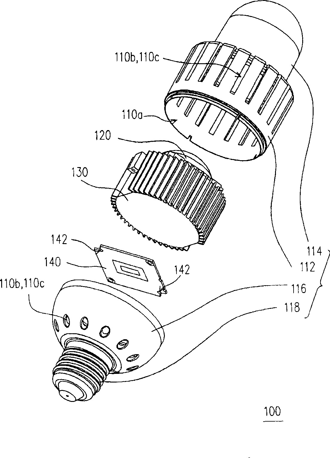
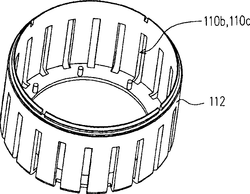
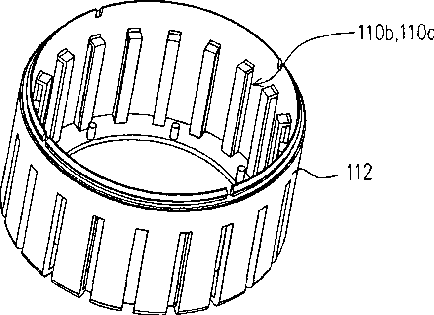
[0050] figure 1 It is a schematic diagram of the LED lamp according to the first embodiment of the present invention. Please refer to figure 1 , the LED lamp 100 of this embodiment includes a lamp housing 110 , an LED light source 120 , a heat sink 130 and a control circuit 140 . The lamp housing 110 has an accommodating space 110a, a plurality of air inlets 110b and a plurality of air outlets 110c, and the accommodating space 110a communicates with the outside through the air inlets 110b and the air outlets 110c. Both the LED light source 120 and the heat sink 130 are disposed in the accommodating space 110 a, and the heat sink 130 is connected to the LED light source 120 , wherein the heat sink 130 includes a base 132 and a plurality of cooling fins 134 connected to the base 132 . Depend on figure 1 It can be seen that there is a gas convection channel 136 between any two adjacent heat dissipation fins 134, and the gas existing in the outside world is suitable for flowing...

no. 2 example

[0063] Figure 4 It is a schematic diagram of an LED lamp according to the second embodiment of the present invention. Please refer to FIG. 2, the light emitting diode lamp 100' of this embodiment is similar to the first embodiment, but the main difference between the two is that: the light emitting diode lamp 100' of this embodiment further includes a The fan 150 , wherein the fan 150 is adapted to force outside air to flow into the accommodating space 110 a from the air inlet 110 b, and leave the accommodating space 110 a through the gas convection channel 136 and the air outlet 110 c in sequence. From Figure 4 It can be seen that the fan 150 is disposed on the base 132 , and the cooling fins 134 surround the fan 150 . When the fan 150 is turned on, the air convection in the accommodating space 110a will be stronger, so that the LED lamp 100' can operate at a lower temperature. It should be noted that, in this embodiment, the fan 150 and the LED light source 120 are resp...

no. 3 example

[0065] Figure 5A and Figure 5B It is a schematic diagram of the relative positions of the fan, the control circuit, the radiator and the LED light source in the third embodiment of the present invention. Please refer to Figure 5A and Figure 5B , similar to the second embodiment in this embodiment, in this embodiment, one side of the heat sink 130 has a first groove 130a to accommodate the LED light source 120, and the control circuit 140 (such as a circuit board) is configured on the other side of the heat sink 130 . In addition, by Figure 5A and Figure 5B It can be seen that the control circuit 140 is located between the fan 150 and the radiator 130 . In this embodiment, the LED light source 120 can be welded on the heat sink 130 by soldering, so that the heat generated by the LED light source 120 can be effectively transferred to the heat sink 130 . Of course, in this embodiment, the bonding between the LED light source 120 and the heat sink 130 can also be perf...


PUM


Abstract

The invention discloses a LED lamp which comprises a lamp shell, a LED light source, a radiator and a control circuit. The lamp shell is provided with a containing space, a plurality of air inlets and air outlets; the containing space is communicated with the external environment through the air inlets and the air outlets. The LED light source and the radiator are all arranged in the containing space; the radiator is connected with the LED light source; wherein, the radiator includes a base and a plurality of heat dissipation fins connected with the base; an airflow convection channel is formed between any two adjacent heat dissipation fins to facilitate the air in the external environment to flow into the containing space from the air inlets and flow out the containing space sequentially through the airflow convection channels and the air outlets. The control circuit is arranged in the lamp shell and electrically connected with the LED light source.

Description

technical field [0001] The present invention relates to a light-emitting diode lamp (light-emitting diode lamp, LED lamp), and in particular to a light-emitting diode lamp with good heat dissipation performance. Background technique [0002] Light-emitting diodes (LEDs) belong to semiconductor components, and the materials of their light-emitting chips mainly use III-V chemical elements, such as compound semiconductors such as gallium phosphide (GaP) and gallium arsenide (GaAs), whose light-emitting principle is to convert electrical energy into Light, that is, applying current to the compound semiconductor, releases excess energy in the form of light through the combination of electrons and holes, and achieves the effect of luminescence. Since the light emitting phenomenon of the light emitting diode is not through heating or discharging, the life of the light emitting diode is as long as more than 100,000 hours, and there is no need for idling time. In addition, LEDs are ...

Claims


Application Information

Patent Timeline
IPC IPC(8): F21V29/02F21V29/00F21V15/02F21V23/00F21Y101/02F21S2/00F21S8/04H01L33/00
CPCH04M1/22Y10S362/80F21V29/004F21V29/02F21K9/00F21W2111/00F21V29/2293F21Y2101/02F21V29/2231F21V29/677F21V29/773F21V29/83F21K9/232F21Y2115/10F21V29/67
Inventor 蔡文贵刘家齐王纯健吴清华
Owner CHANG WAH ELECTROMATERIALS INC
Why Eureka
Try Eureka