
Rail type conveyer

A conveyor, track-type technology, applied in conveyors, mechanical conveyors, transportation and packaging, etc., can solve the problems of easy chain jumping, chain breakage, insufficient transfer speed, etc., to achieve convenient clamping distance, easy installation and disassembly , the effect of fast delivery

Inactive Publication Date: 2009-02-18
湖北恒普自动化装备有限公司
View PDF0 Cites 40 Cited by
  • Summary
  • Abstract
  • Description
  • Claims
  • Application Information

AI Technical Summary

Problems solved by technology

Before the present invention was proposed, the automatic packaging production line of civil explosives generally used traditional chain conveying equipment or belt transmission equipment for the transfer of tundish clips, and the distance could not be changed during the transfer, and the displacement conversion speed of these equipment was very fast. Under ground conditions, the stability becomes poor, and there are deficiencies such as insufficient transfer speed, or the chain moves back and forth at high speed and is easy to skip teeth.
If it is a chain drive, the chain may often break during the long-term reciprocating operation, which cannot meet the high-speed transportation and cannot be opened according to the predetermined distance, so that the alignment of the clips cannot be aligned with the rear end. The pushing position of the charter plane matches

Method used


Image

  • Rail type conveyer
  • Rail type conveyer
  • Rail type conveyer

Examples


Embodiment Construction

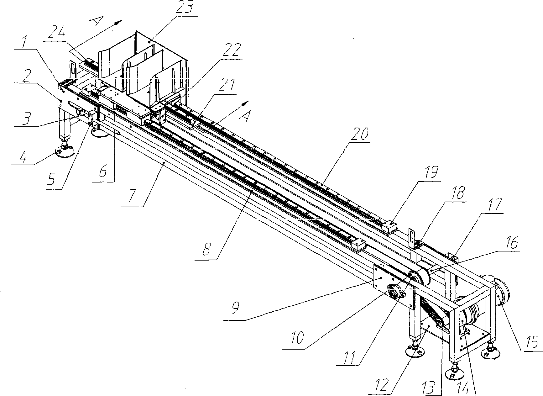
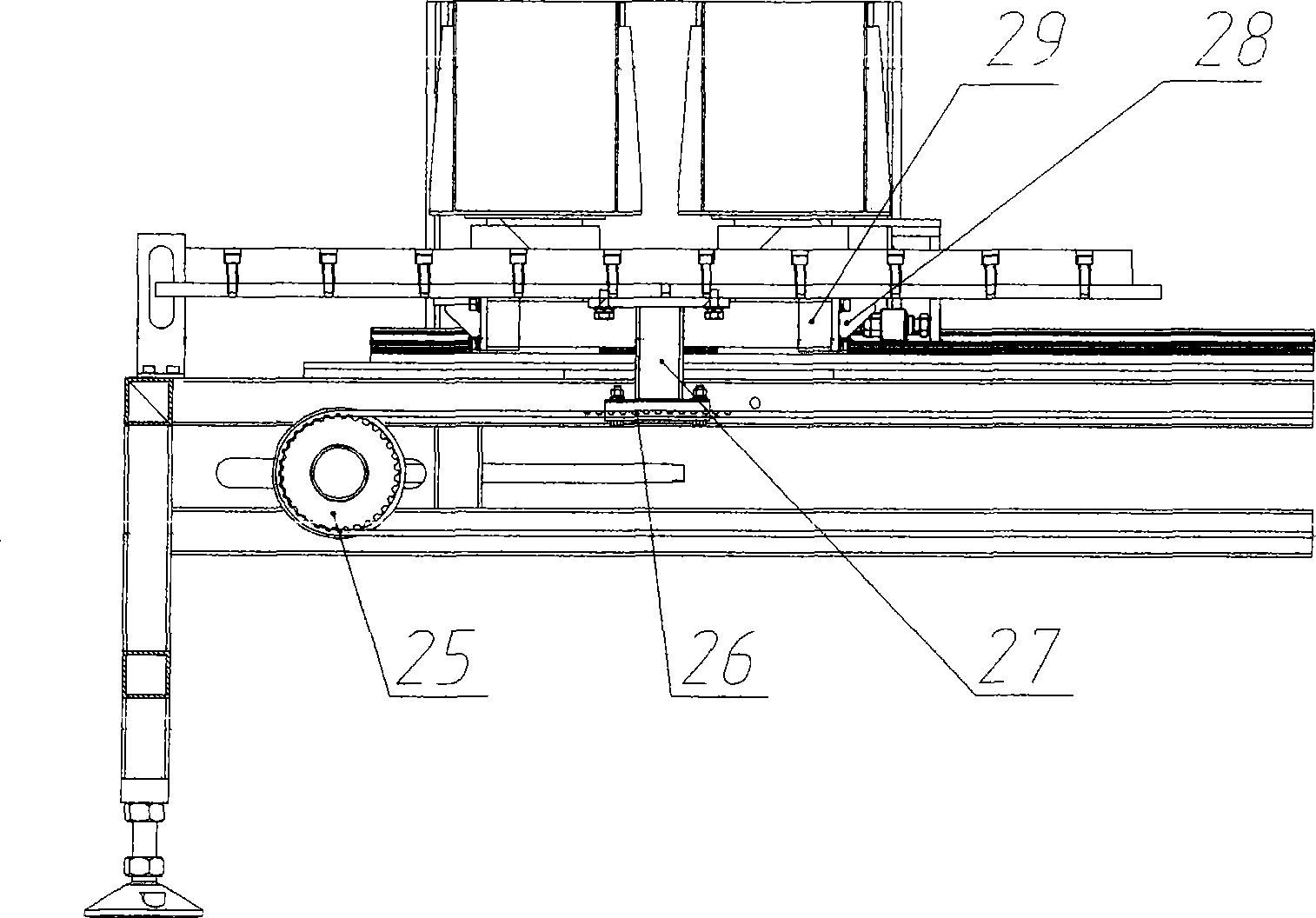
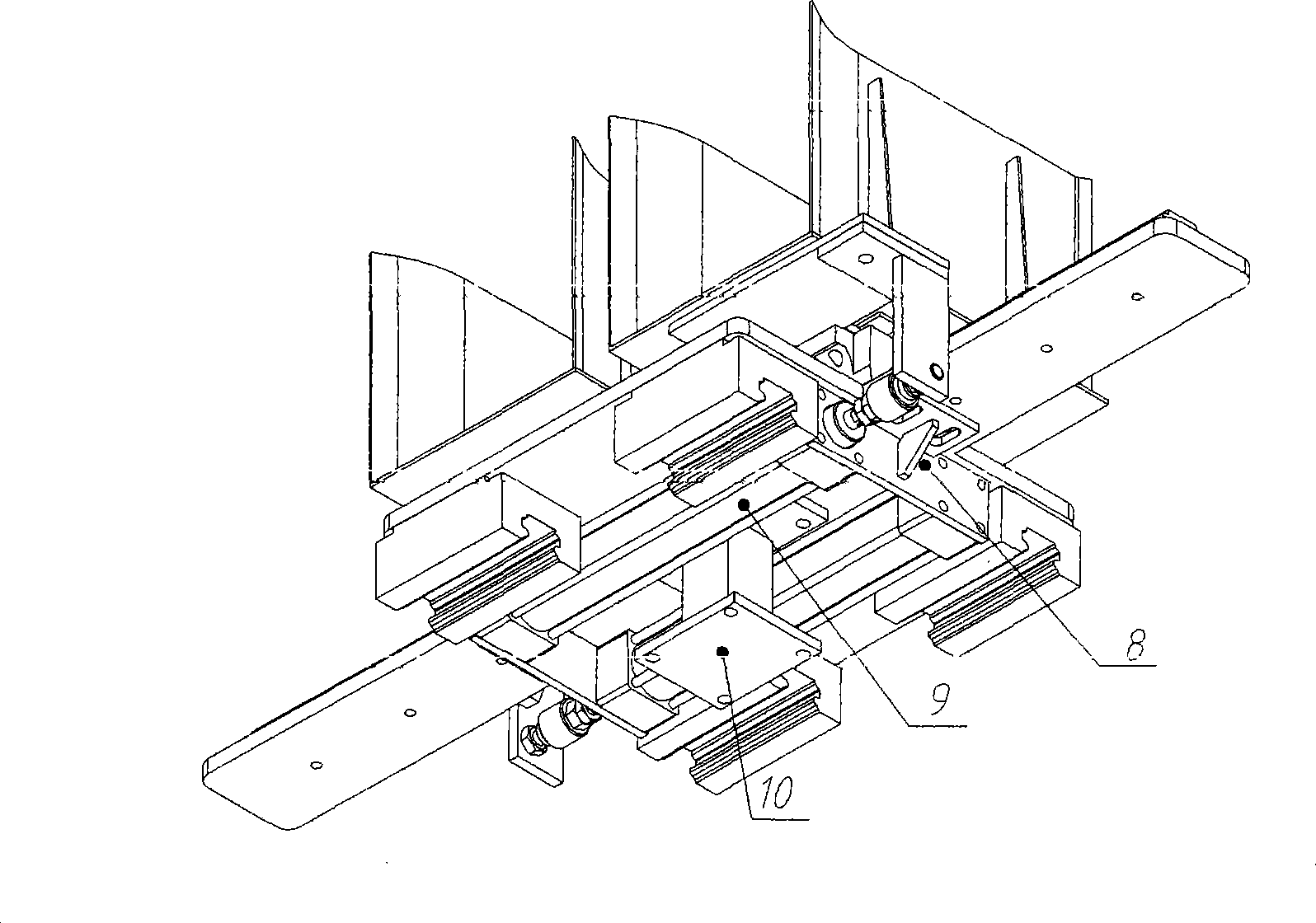
[0018] see Figure 1 to Figure 3 , the track conveyor of the present invention mainly consists of a driven wheel mounting plate 1, a wheel shaft 2 of a driven pulley, a tension screw 3, a universal foot 4, a tension seat 5, a clip 6, a frame 7, a long Guide rail mounting plate 8, driving wheel mounting plate 9, driving pulley 10, driven wheel at motor end 11, motor seat plate 12, driving wheel at motor end 13, reducer 14, motor 15, wheel shaft 16 of driving pulley, rotary encoder 17. Sensor 18, limit block 19, long linear guide rail 20, short guide rail mounting plate 21, L-shaped support 22, drug volume baffle plate 23, short linear guide rail 24, driven pulley 25, toothed plate 26, connection Block 27, cylinder mount 28 and cylinder 29 constitute.

[0019] The driven wheel mounting plate 1 is fixed on the rear end of the frame 7 with hexagonal bolts, the wheel shaft 2 of the driven pulley is fixed on the oblong hole of the driven wheel mounting plate 1, and the tension seat...


PUM


Abstract

A track-type conveyor comprises a machine rack, a drive belt wheel, a drive belt wheel, a synchronous belt, a motor, a long linear guide rail, clips and a clip support mechanism; the drive belt wheel and the driven belt wheel are respectively fixed on the machine rack; the long linear guide rail is arranged on the machine rack; the clips are respectively positioned on two clip spacer plates on the clip support mechanism which can realize the displacement transformation among clips; each clip spacer plate in the clip support mechanism is matched with a short linear guide rail in the clip support mechanism through a clip slider connected with the clip spacer plate; the clip spacer plate is driven by a drive mechanism which is fixed in a short guide rail mounting plate to enable the two clip spacer plates to be furled and opened along the short linear guide rail; and the short guide rail mounting plate of the clip support mechanism is connected with the synchronous belt and also matched with the long linear guide rail through a main slider connected with the short guide rail mounting plate. The invention is characterized by simple structure, small size, easy installation and detachment, as well as fast delivery speed, which can rapidly deliver the packages conveyed from an automatic clip feeder to the predetermined locations in accordance with the scheduled itinerary.

Description

technical field [0001] The invention belongs to the field of packaging machinery, and in particular relates to a front-end automatic clamping mechanism of a civilian explosive automatic tundish production line and a drug roll transfer rail conveyor after rolling. Background technique [0002] The middle pack of civil explosives refers to a pack of explosive rolls arranged in four horizontal rows and five vertical rows (4×5). Before the present invention was proposed, the automatic packaging production line of civil explosives generally used traditional chain conveying equipment or belt transmission equipment for the transfer of tundish clips, and the distance could not be changed during the transfer, and the displacement conversion speed of these equipment was very fast. Under ground conditions, the stability becomes poor, and there are deficiencies such as insufficient transfer speed, or the chain moves back and forth at high speed and is easy to skip teeth. If it is a cha...

Claims


Application Information

Patent Timeline
IPC IPC(8): F42B39/00B65G35/00B65G25/06
Inventor 方磊姜卫国李怀刚王云亮柴广宇周珉田传红向同燕
Owner 湖北恒普自动化装备有限公司
Learn More