Optical micro-control system and operation control method thereof

A manipulation system and optical technology, applied in the field of optical micro manipulation systems, can solve the problems of lack of timely correction, inadequate operation, complicated correspondence, etc., so as to achieve functional expansion, extension of application scope, and good flexibility. Effect

Inactive Publication Date: 2009-02-25
高秀敏 +1
View PDF1 Cites 8 Cited by
  • Summary
  • Abstract
  • Description
  • Claims
  • Application Information

AI Technical Summary

Problems solved by technology

However, due to the various forms of this operation, the correspondence between phase adjustment and each operation form is also very complicated, the particles themselves and the solution also have certain uncertainties, and often there are situations where the operation is not in place or the operation is wrong, making The operation is not accurate, the most important thing is that it cannot be corrected in time
Caused many problems in the practical application of optical tweezers

Method used


Image

  • Optical micro-control system and operation control method thereof

Examples


Embodiment

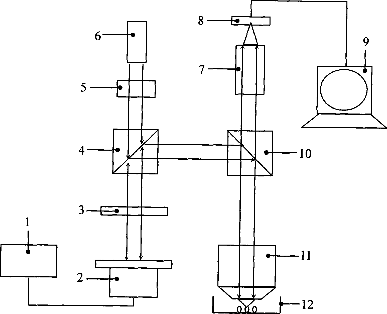
[0023] The following part of this example describes an optical micromanipulation system:

[0024] Such as figure 1 As shown, the optical micro-manipulation system includes a light source 6, a beam-containing device 5, a polarizing beam splitter 4, a quarter-wave plate 3, a reflective phase adjustment device 2, a spectral beam splitter 10, an imaging mirror group 7, a CMOS device 8, The monitor 9 and the objective lens 11 are provided with a beam-containing device 5, a polarizing beam splitter 4, a quarter-wave plate 3 and a reflective phase adjustment device 2 in sequence directly below the light source 6, and the reflective phase adjustment device 2 is controlled by a controller 1. control, the reflection path of the polarization beam splitter 4 is provided with a spectral beam splitter 10, the objective lens 11 is arranged directly below the spectral beam splitter 10, the imaging mirror group 7 and the CMOS device 8 are arranged directly above the spectral beam splitter 10 i...


PUM


Abstract

The invention relates to an optical micro-control system and a control method thereof, and is mainly used in the fields of laser micro-machining, optical micro-control, optical information storage, interaction between light and matter and the like. The system is composed of a light source, a light splitter, a reflecting phase regulator and an object lens; the light splitter and the reflecting phase regulator, as well as a spectrum spectroscope and a microscope system, are sequentially arranged in the advance direction of a light beam emitted by the light source; the spectrum spectroscope is arranged on the reflecting light path of the light splitter; the object lens is arranged on the reflecting light path of the spectrum spectroscope; the microscope system is arranged on an extension line of the reflecting light path of the spectrum spectroscope; and the microscope system and the object lens are respectively arranged on the two sides of the spectrum spectroscope.

Description

technical field [0001] The invention relates to an optical micro-manipulation system, in particular to an adjustable wave front phase optical micro-manipulation system and a control method thereof. It is mainly used in the fields of laser micromachining, optical micromanipulation, optical information storage, and interaction between light and matter. technical background [0002] Optical micromanipulation system refers to the system that utilizes optomechanical effects such as optical gradient force and scattering force to manipulate and trap tiny particles. The particles that can be captured by the optical micromanipulation system can range from a few nanometers to tens of microns, which can be inanimate particles, living cells or viruses, etc. The research on light beam levitation and trapping of tiny particles can be traced back to the 1970s. The system to realize light levitation and trapping of tiny particles was successfully developed by Ashkin's research group, and w...

Claims


Application Information

Patent Timeline
Patent Type & Authority Applications(China)
IPC IPC(8): G02B26/06G02F1/01G02B21/36
Inventor 高秀敏陈俊志
Owner 高秀敏
Why Eureka
Try Eureka