Ink supply mechanism and stepping motor driver therefor

A stepper motor, motor technology, applied in the general parts of printing machinery, printing presses, printing and other directions, can solve the problems of deterioration acceleration, wear time, damage, etc., and achieve the effect of reducing noise, reducing wear or damage

Inactive Publication Date: 2009-03-04
COPAL ELECTRON CO LTD
View PDF2 Cites 2 Cited by
  • Summary
  • Abstract
  • Description
  • Claims
  • Application Information

AI Technical Summary

Problems solved by technology

In addition, the strength of the rotating sound changes due to changes in the load and the accompanying changes in the number of revolutions, resulting in a harsh sound
(2) When used in a printing machine, if the load changes, the operating current and the number of revolutions will change
That is to say, even if the cause of the load fluctuation is due to mechanical failure (such as damage, etc.), the DC motor will generate torque according to its characteristics (for example, even if the load does not move, it will increase the torque required to change the load. current that compulsively generates torque), resulting in damage, wear and deterioration over time, acceleration, etc.
(3) The target arrival position (time) or stop position (time) is prone to deviate due to load changes or changes in the number of revolutions
Therefore, it is very susceptible to dirt and loads near the output shaft and pinion

Method used


Image

  • Ink supply mechanism and stepping motor driver therefor
  • Ink supply mechanism and stepping motor driver therefor
  • Ink supply mechanism and stepping motor driver therefor

Examples


Embodiment Construction

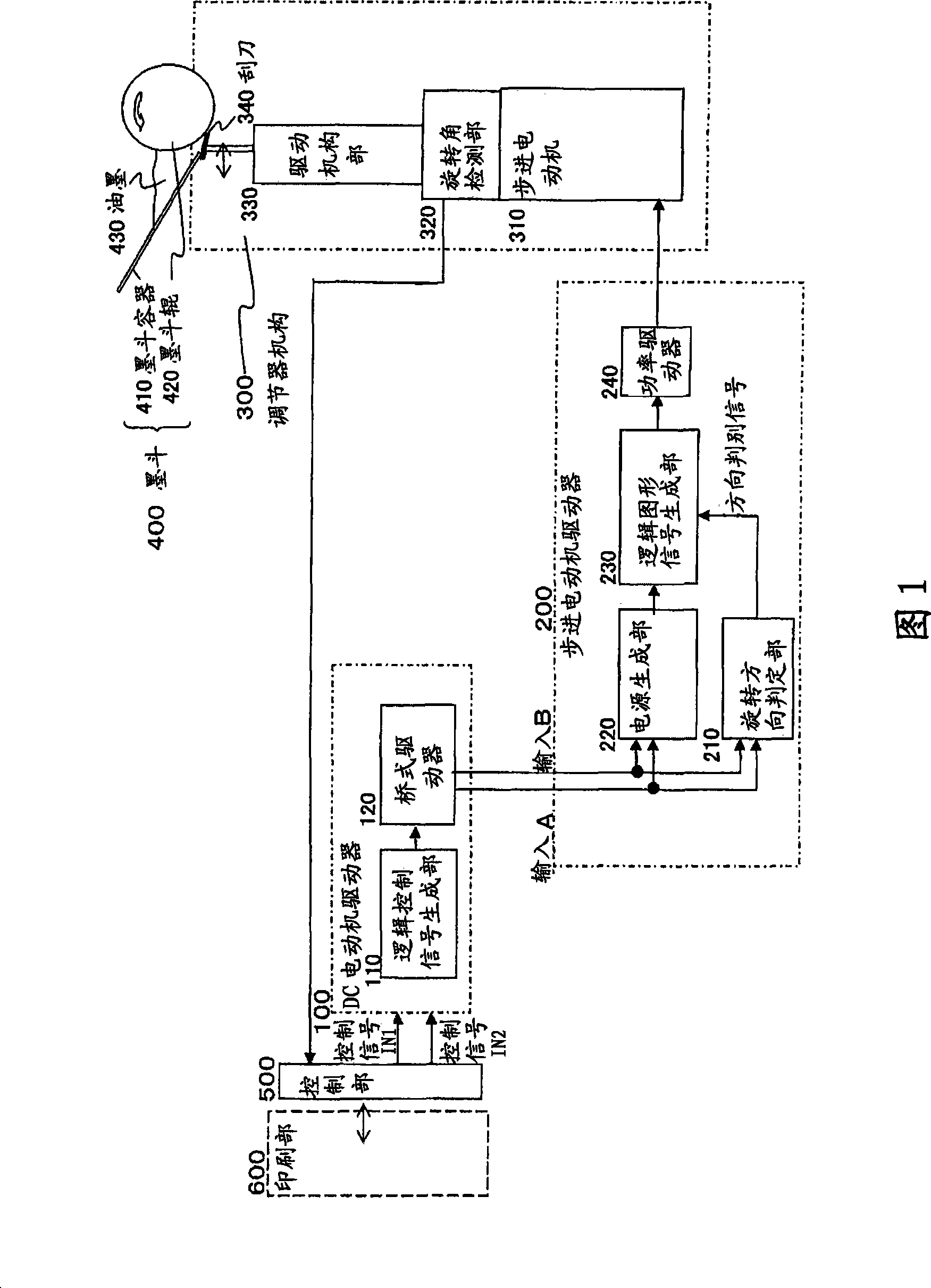
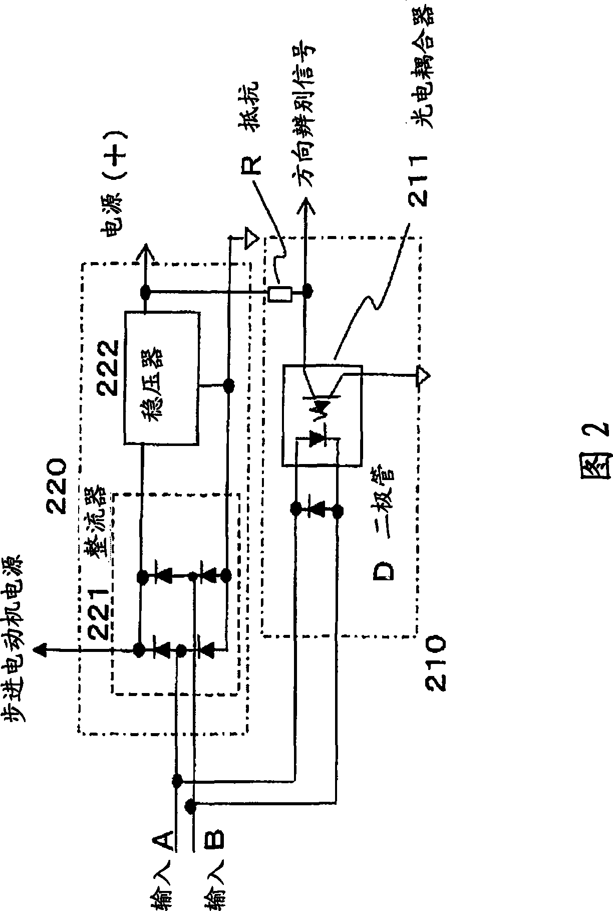
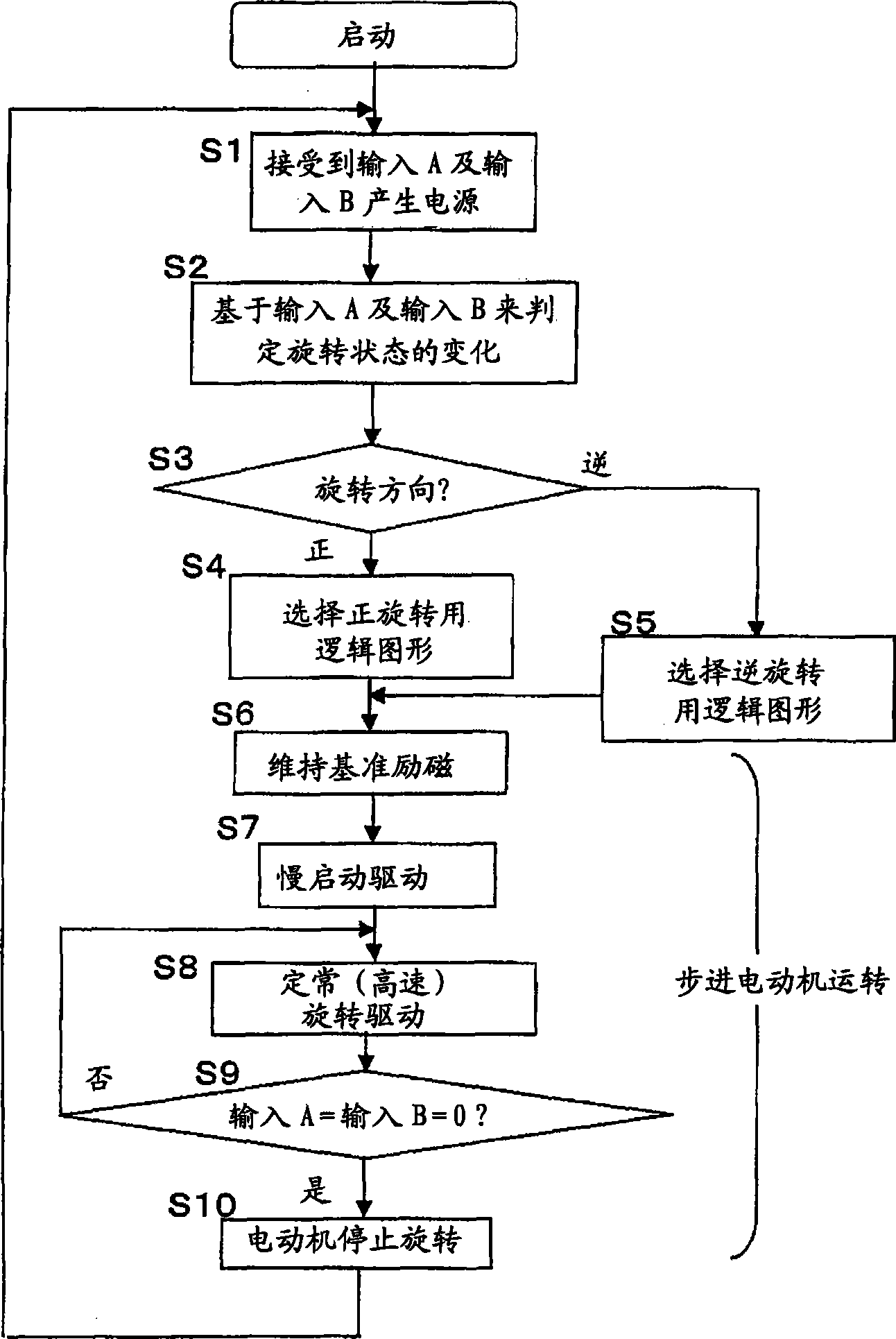
[0050] Embodiments of the present invention will be described using the drawings. Fig. 1 is a diagram showing a functional structure of an embodiment of the present invention. FIG. 2 is a diagram illustrating details of a power generation unit and a rotation direction determination unit in FIG. 1 . image 3 It is a diagram showing the operation flow of the stepping motor driver in FIG. 1 . FIG. 4 is an illustration of logic pattern signals used to drive a stepping motor. Figure 5 It is a graph showing the change of the signal value of the logic pattern in FIG. 4 . Figure 6 It is a graph showing the input and output values ​​of the DC motor driver.

[0051] In FIG. 1 , the background art part and the present invention part are separated, as described in (A) and (B) below. That is, (A) the control part 500, the printing part 600, the DC motor driver 100, the actuator mechanism 300 and the ink fountain 400 except the stepping motor 310 are the background technology, (B) inst...


PUM


Abstract

In the invention, the DC motor for driving printing ink supplying quantity regulating scraper can be replaced by a step motor, and the step motor can be driven by the same control signal with the DC motor. The DC motor is replaced by the step motor (310); and the DC motor driver (100) as driving unit for providing analog voltage is remained; the analog voltage is used for driving the DC motor to rotate, reversely rotate or stop; a step motor driver (200) is disposed between the DC motor driver (100) and the step motor for generating power source from the analog voltage used for driving the DC motor and generating logic figure signal to drive the step motor.

Description

technical field [0001] The present invention relates to an ink supply mechanism for adjusting the amount of ink supplied from an ink fountain in an ink fountain used in a printing machine, and a stepping motor driver used for the ink supply mechanism. In particular, the present invention relates to a technique of adjusting the space between the doctor blade and the ink fountain roller by moving and adjusting the doctor blade when the ink in the ink fountain is attached to the ink fountain roller and the ink is supplied to the doctor blade, thereby To adjust the supply amount, at this time, it is easy to change the motor as the power source for movement adjustment from a DC motor to a stepping motor. Background technique [0002] In the past, the amount of ink supplied from the ink fountain in the printing press was adjusted by adjusting the distance between the ink fountain roller and the doctor blade arranged at the ink outlet to an appropriate interval. Usually, the ink f...

Claims


Application Information

Patent Timeline
Patent Type & Authority Applications(China)
IPC IPC(8): B41F31/12B41F31/04B41F31/32B41F33/10
Inventor 新井清之大竹裕三浦刚史手吕内贤二
Owner COPAL ELECTRON CO LTD
Why Eureka
Try Eureka