Supercharge Your Innovation With Domain-Expert AI Agents!

Valve unit with electronic valve recognition devices

A technology of electronic devices and valves, applied in the direction of valve devices, fluid pressure actuating devices, valve details, etc., to achieve the effect of saving reading units

Active Publication Date: 2013-11-27
ROBERT BOSCH GMBH
View PDF1 Cites 0 Cited by
  • Summary
  • Abstract
  • Description
  • Claims
  • Application Information

AI Technical Summary

Problems solved by technology

The disadvantage of this solution resulting from this is the high complexity associated with the electronic assembly, since a unique reading device is assigned to each individual basic element side transceiver

Method used


Image

  • Valve unit with electronic valve recognition devices
  • Valve unit with electronic valve recognition devices

Examples


Embodiment Construction

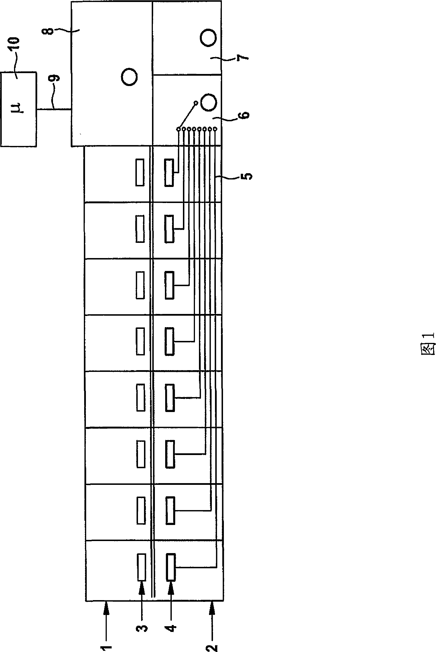
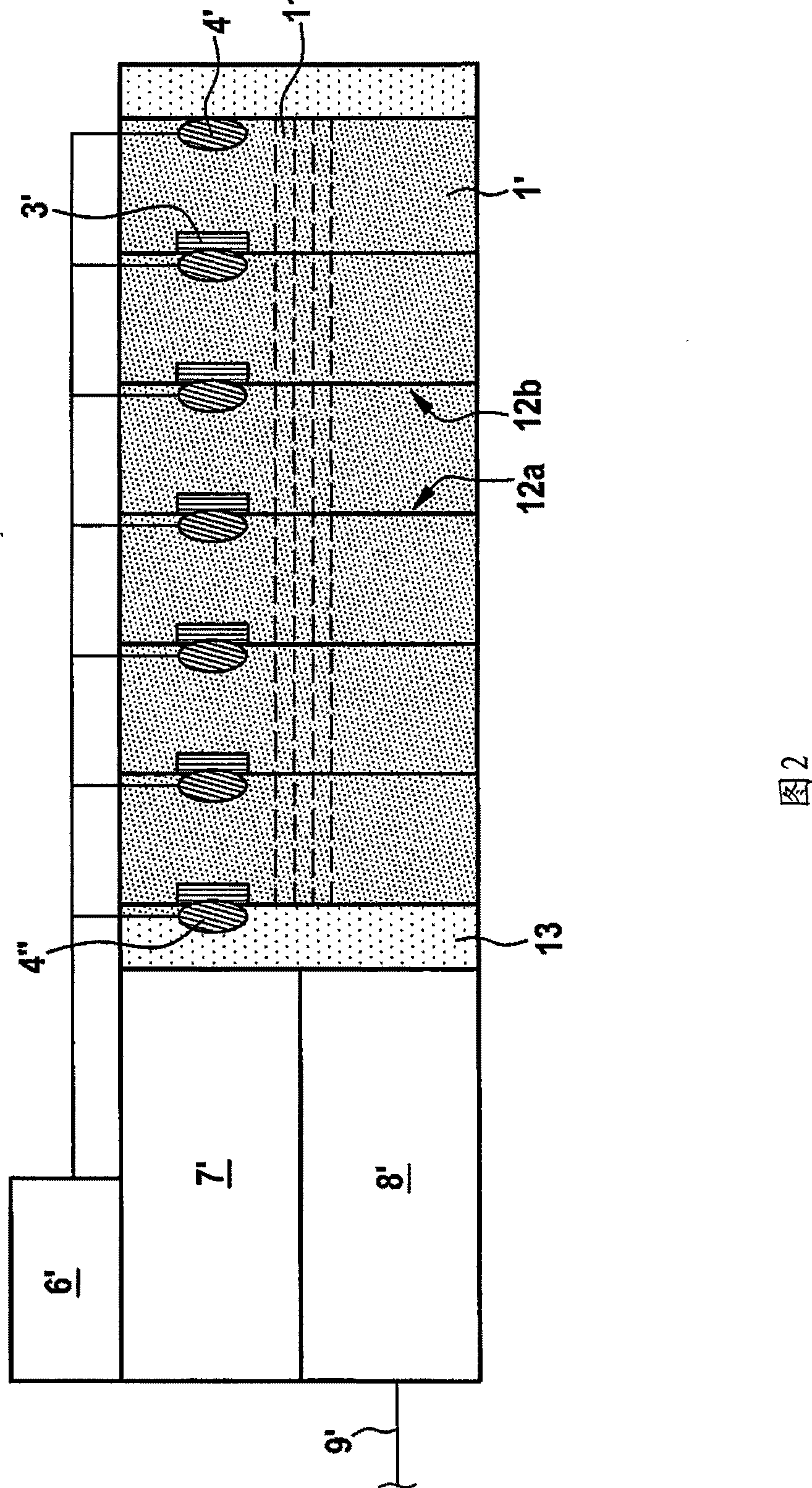
[0016] according to figure 1 , the valve unit consists of a plurality of electro-pneumatic valves (1) connected together, the fluid and electrical connections of which are produced by means of individually assigned base elements (2). The individual base elements ( 2 ) are likewise connected together and have a common channel guide (not shown) for the fluid supply.

[0017] Each valve (1) contains an electronic transceiver in which the identification of the valve in the form of a serial number, the identification of the function of the valve, the date of manufacture and the identification of the batch number are stored.

[0018] The reading means assigned to each transceiver (3) on the side of the base element (2) comprises a plurality of individual RFID read heads (4), via parallel lines with individual signal transmission lines (5), each The read head leads to the entrance of a multiplexer unit (6). In order to read the individually assigned information content of each tran...


PUM


Abstract

The unit has valves (1) for switching compressed air flow, where each valve is attached to a base element (2) for fluid and electrical connection. Multiple electronic units are provided for detection of a valve. Each electronic unit has a valve-side transponder (3) and a base element-side reading device. The reading device has individual radio-frequency identification (RFID) reading heads (4) attached to a respective transponder, and a RFID-reading unit (7) is provided common to all RFID reading heads. The RFID reading heads are connected to the RFID-reading unit by a multiplexer unit (6).

Description

technical field [0001] The invention relates to a valve unit for switching compressed air flows with a plurality of valves connected together, wherein each valve is assigned to at least one basic element of the system for fluid and / or electronic applications and is provided with a separate Valve detection electronics consisting of transponders on the valve side and reading devices on the base element side. Background technique [0002] The scope of application of the pneumatic valve unit mainly extends to the pneumatic automatic control system, with which the machining process is carried out. In one valve unit, there are several valves for controlling pneumatic components (such as air cylinders) that are combined together at a local location and can thus be supplied with compressed air and electronic control signals in a central supply . The valve unit can also have a plurality of valves whose basic elements are integrated directly into the housing, wherein the channel sec...

Claims


Application Information

Patent Timeline
Patent Type & Authority Patents(China)
IPC IPC(8): F16K37/00F16K11/22F16K27/00
CPCF15B13/0867F16K27/003G06K7/0008G06K19/14
Inventor 赫伯特·克雷布斯弗朗克·雅各布斯
Owner ROBERT BOSCH GMBH
Features
  • R&D
  • Intellectual Property
  • Life Sciences
  • Materials
  • Tech Scout
  • Unparalleled Data Quality
  • Higher Quality Content
  • 60% Fewer Hallucinations
Learn More