heat exchanger

A technology of heat exchangers and heat generators, applied in the direction of heat exchange equipment, indirect heat exchangers, heat exchanger types, etc., to achieve the effects of reliability improvement, optimization of boiling and condensation performance, and cost reduction

Active Publication Date: 2012-02-22
ABB (SCHWEIZ) AG
View PDF2 Cites 1 Cited by
  • Summary
  • Abstract
  • Description
  • Claims
  • Application Information

AI Technical Summary

Problems solved by technology

This imposes strict low-cost conditions on its design

Method used


Image

  • heat exchanger
  • heat exchanger
  • heat exchanger

Examples


Embodiment Construction

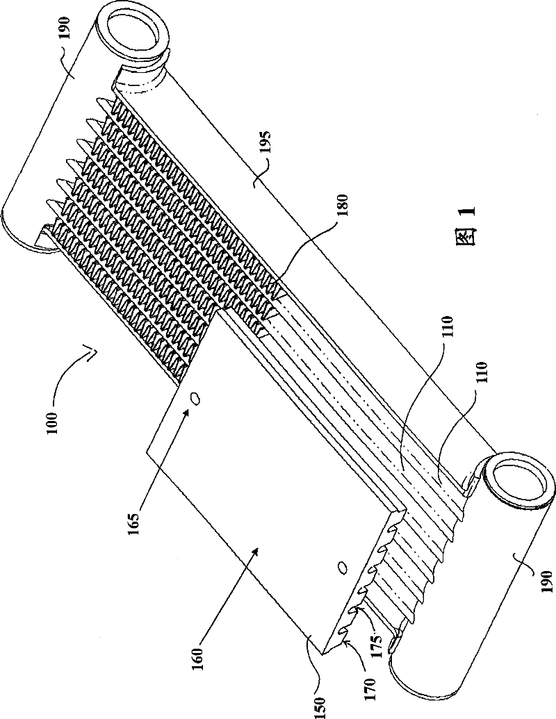
[0055] refer to figure 1 A heat exchanger 100 according to a first preferred embodiment of the present invention is described.

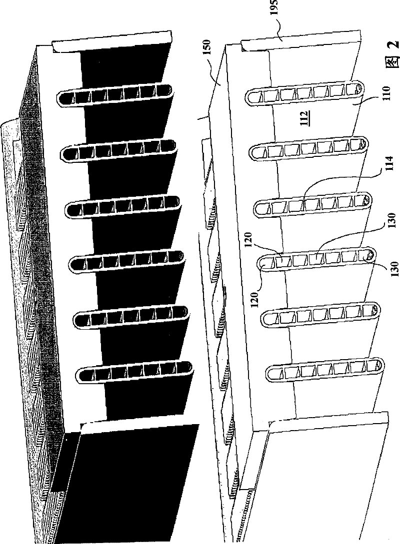
[0056] Such as figure 1 As shown, the heat exchanger 100 includes a plurality of conduits 110 for the working fluid, each conduit 110 has an outer wall 112, and each conduit 110 has a structure for forming at least one evaporation channel 120 and at least one condensation channel in the conduit 110. The inner wall 114 of the road 130 (refer to figure 2 ). Furthermore, the heat exchanger comprises a first heat transfer element 150 for transferring heat to the evaporation channel and a second heat transfer element 180 for transferring heat away from the condensation channel. The conduit 110 is arranged in a vertical position, but other positions of at least 45° are also possible. The evaporation channels 120 and the condensation channels 130 are aligned in parallel within the conduit 110 .

[0057] exist figure 1 In the illustrated embodiment, t...


PUM


Abstract

The present invention provides a heat exchanger (100) for removing heat energy from a heat generator (200), comprising at least one conduit (110) for a working fluid, which is arranged in an upright position of at least 45°, each conduit having an exterior wall (112) and at least one interior wall (114) for forming at least one evaporator channel (120) and at least one condenser channel (130) within the conduit (110). Furthermore, the heat exchanger (100) comprises a first heat transfer element (150; 183) for transferring heat into the evaporator channel (120) and a second heat transfer element (180) for transferring heat out of the condenser channel (130).

Description

technical field [0001] The present invention generally relates to a heat exchanger. In particular, the invention relates to a heat exchanger that can be used in power electronics. Background technique [0002] Low voltage drive systems have a competitive market among global players. This imposes a strict low cost condition on its design. In a typical system, power electronic components such as discrete or integrated (ie module type) semiconductor components, inductors, resistors, capacitors and copper bus bars are packed in close proximity. PCB panels and control electronics are also present on all designs. During operation, these elements emit variable amounts of heat. Additionally, these components can tolerate variable levels of temperature. The ambient conditions of the surround drive system also vary in terms of air temperature, humidity, dust and chemical content. In addition to the electrical performance of the system, the thermal management and integration conc...

Claims


Application Information

Patent Timeline
Patent Type & Authority Patents(China)
IPC IPC(8): F28D15/02H05K7/20
CPCF28D15/0233F28D15/0275F28D2021/0029F28D2021/0031F28D1/05383F28D15/0266F28F2013/005F28F1/126Y10T29/49364
Inventor B·耶辛B·阿戈斯蒂尼
Owner ABB (SCHWEIZ) AG
Why Eureka
Try Eureka