Surface conditioning for thermal spray layers

A thermal spray coating, metal surface technology, applied in the direction of coating, metal material coating process, melt spraying, etc.

Inactive Publication Date: 2009-03-04
DAIMLER AG
View PDF3 Cites 23 Cited by
  • Summary
  • Abstract
  • Description
  • Claims
  • Application Information

AI Technical Summary

Problems solved by technology

[0012] Known methods for pretreatment or conditioning of surfaces are not sufficient to obtain thermally sprayed coatings with sufficient adhesion strength under conditions of thermal alternating loads and mechanical stress

Method used


Image

  • Surface conditioning for thermal spray layers
  • Surface conditioning for thermal spray layers
  • Surface conditioning for thermal spray layers

Examples


Embodiment Construction

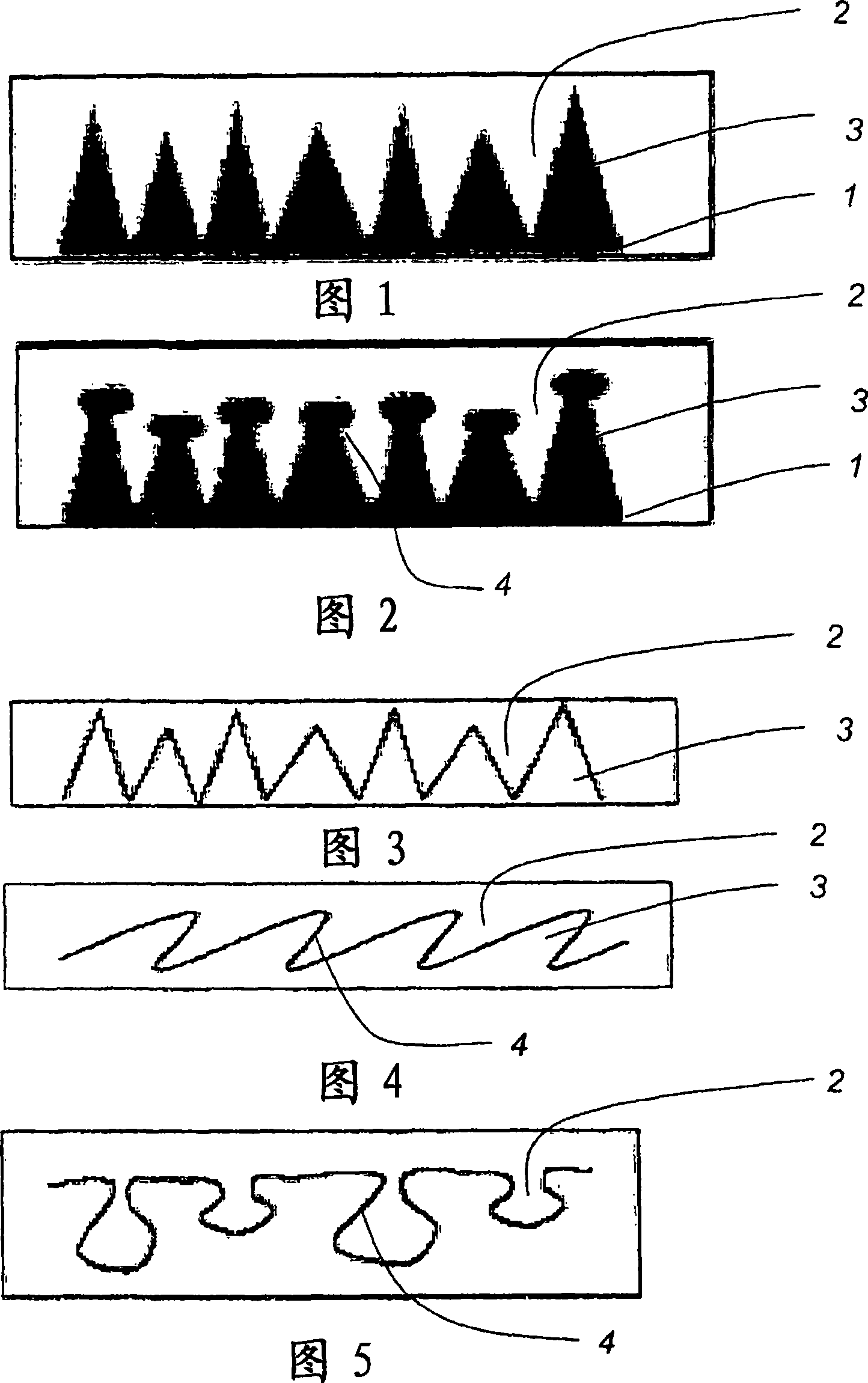
[0031] In a preferred embodiment of the second step, the surface roughened by the first step is rolled, pressed or sprayed with a solid and / or liquid medium.

[0032] A possible effect of this second process step is schematically shown in FIG. 4 . In the first working step, grooves are machined in the surface (Fig. 3). The protruding microstructures (3) in the shape of the flutes are then bent laterally. This is done, for example, by a rolling process. A preferred orientation of the curved or bent microstructures can likewise be achieved by an obliquely acting injection process or extrusion process.

[0033] In particular, spraying is suitable for uniformly bending or bending protruding structures in all directions. Suitable blasting media are, for example, fine, nearly round powders, which have little abrasive action, especially compared to shot peening.

[0034] The blasting of the second process step can likewise be carried out using mild abrasive conditions, for exampl...


PUM


Abstract

The invention relates to a process for roughening metal surfaces to improve adhesion of layers which are thermally sprayed onto the surface, in which, in a first process step, recesses or depressions (2) are introduced into the surface in a material-detaching or material-removing treatment so that the remaining metal of the surface forms raised microstructures (3), in particular projections, ridges, protuberances or bumps, with these microstructures being further worked in at least one further process step by shaping and / or breaking so that a significant proportion of the structures forms undercuts (4) in relation to the surface.

Description

technical field [0001] The present invention relates to a method for roughening metal surfaces in order to improve the adhesion of thermal spray coatings on said metal surfaces, and in particular to preparing the surface in thermal coating inside cylinder bores and having a profile suitable for the deposition of thermal spray coatings. Motor vehicle metal components with rough surfaces. Background technique [0002] If thermally sprayed coatings are deposited on metal substrates, high mechanical stresses which adversely affect the adhesion of the coating usually occur due to the large temperature differences between the sprayed coating and the substrate. In conventional thermal spraying methods such as plasma spraying, flame spraying, high velocity flame spraying or wire arc spraying, spray particles in a molten state are deposited on a cold substrate and quenched at high cooling rates. [0003] Likewise, the different mechanical and thermal properties of the coating and th...

Claims


Application Information

Patent Timeline
Patent Type & Authority Applications(China)
IPC IPC(8): C23C4/02
CPCY10T29/47C23C4/02Y10T428/24355
Inventor J·博姆M·格吕纳M·哈特维格T·海尔克K·侯蒂克P·伊兹奎尔多W·佩尔科菲尔D·施灵
Owner DAIMLER AG
Why Eureka
Try Eureka