Continuously variable transmission control device, continuously variable transmission, and vehicle equipped with the same

A continuously variable transmission and control device technology, applied in the direction of transmission, toothed elements, transmission control, etc., can solve the problems of poor riding experience, uneven acceleration, etc., to avoid the reduction of driving comfort. Effect

Active Publication Date: 2009-03-11
YAMAHA MOTOR CO LTD
View PDF8 Cites 20 Cited by
  • Summary
  • Abstract
  • Description
  • Claims
  • Application Information

AI Technical Summary

Problems solved by technology

In addition, if the pulley position control for sliding the movable sheave of the primary pulley to change the transmission ratio is started in this state, the belt to which the force is not transmitt

Method used


Image

  • Continuously variable transmission control device, continuously variable transmission, and vehicle equipped with the same
  • Continuously variable transmission control device, continuously variable transmission, and vehicle equipped with the same
  • Continuously variable transmission control device, continuously variable transmission, and vehicle equipped with the same

Examples


no. 1 example

[0065]

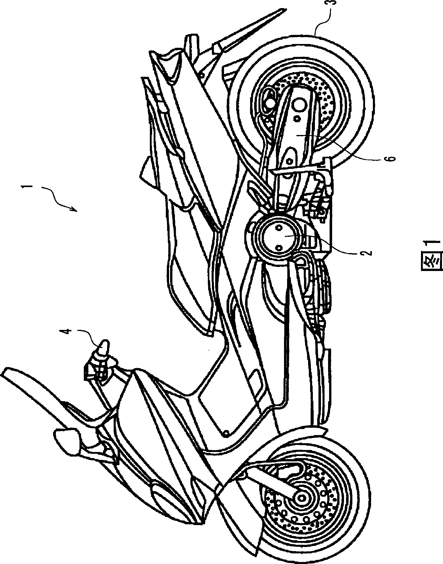
[0066] In this embodiment, a scooter type motorcycle 1 will be explained as an example of an embodiment of the present invention. As shown in FIG. 1, a motorcycle 1 includes a handlebar 4, a power unit 2, and a rear wheel 3 as a driving wheel.

[0067] (handles 4)

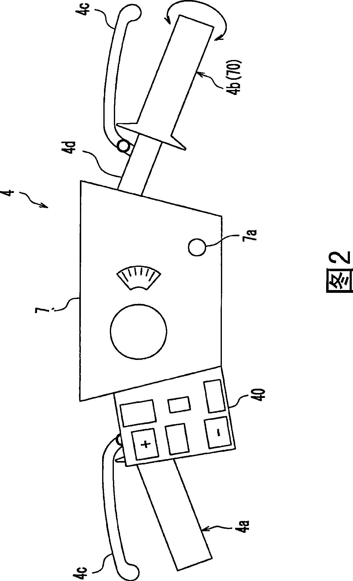
[0068] FIG. 2 shows a schematic view of the structure of the handlebar 4 . The handlebar 4 includes a handlebar stem 4d connected to a steering head pipe not shown. The handlebar 4 includes a left grip portion 4a at the left end of the handlebar stem 4d and a right grip portion 4b at the right end of the handlebar stem 4d. The right grip portion 4b is rotatable about the handlebar stem 4d. If the rider turns the right handle portion 4b, the throttle valve 70 as shown in FIG. 3 is operated and the throttle opening degree is adjusted.

[0069] A brake lever 4c is located adjacent to each of the handle portions 4a, 4b. When a rider operating these brake levers 4c operates the brakes (not shown) of the ...

no. 2 example —

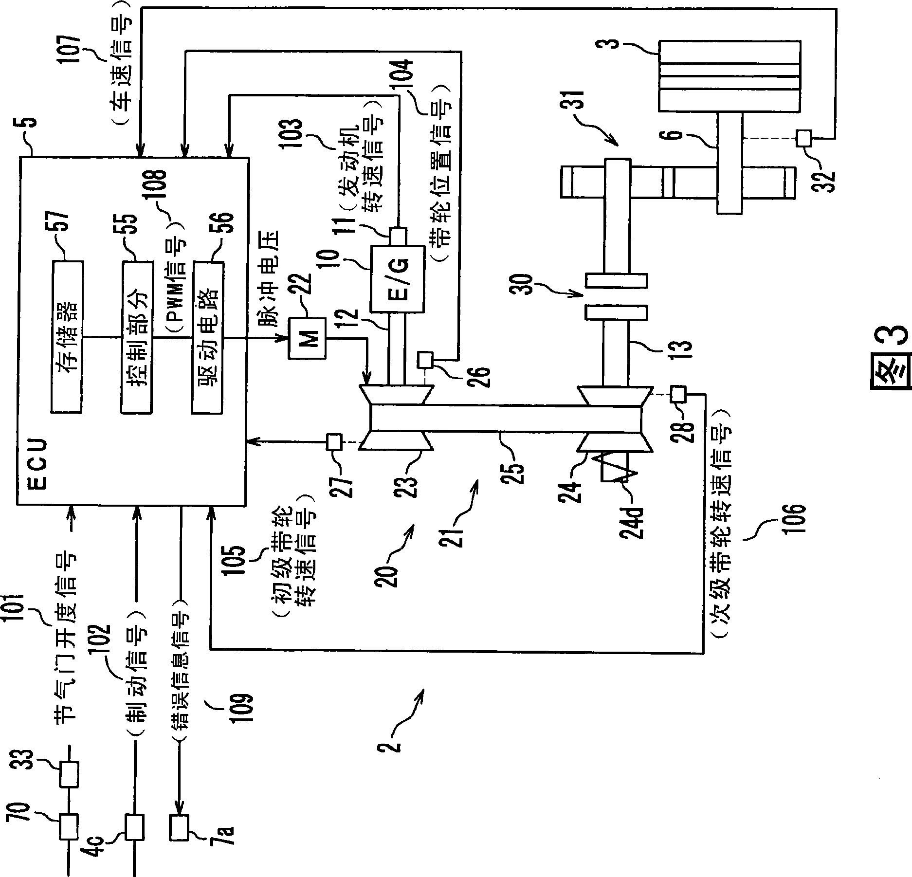
[0138] FIG. 11 is a block diagram showing a continuously variable transmission 260 and a control system of a motorcycle according to the second embodiment. Also, according to the second embodiment, the transmission 260 is a belt-type ECVT. However, the belt of the transmission 260 according to the second embodiment is a so-called metal belt 264 .

[0139] According to a first embodiment, the actuator of the ECVT is the electric motor 22 (see FIG. 3 ). However, the actuator of the ECVT is not necessarily limited to the electric motor 22 . According to a second embodiment explained hereafter, the actuator of the ECVT is a hydraulic actuator.

[0140] Furthermore, as shown in FIG. 3 , the clutch according to the first embodiment is located in the transmission 20 between the output shaft 13 and the rear wheels 3 . In contrast, the clutch according to the second embodiment is a multi-plate friction clutch 265 located between the engine 10 and the input shaft 271 of the transmiss...


PUM


Abstract

The invention provides a control device for a continuously variable transmission, the continuously variable transmission and vehicles with the same, and avoids reduction of driving comfort caused by idling of a primary belt wheel relative to a belt during acceleration. The transmission (20) comprises an input shaft (12), an output shaft (13), the primary belt wheel (23) rotating along with the input shaft (12), and the belt (25) wound around the primary belt wheel (23) and a secondary belt wheel (24). The transmission (20) comprises an electric motor (22) through driving a movable belt wheel (23a) of the primary belt wheel (23) to change variation ratio. The control device (ECU5) of the transmission (20) comprises a rotary secondary belt wheel rotating speed sensor (28) of a detection tape (25), and a control part (55) of the ECU (5) controls the position of the belt wheel after being started to detect out the rotation of the tape (25), namely, normal control of the variation ratio.

Description

technical field [0001] The present invention relates to a continuously variable transmission control device, a continuously variable transmission and a vehicle equipped with them. Background technique [0002] In the prior art, an electronically controlled continuously variable transmission (hereinafter, referred to as "ECVT" (Electrically Controlled Continuously Variable Transmission)) capable of continuously changing the gear ratio is used in scooter motorcycles, so-called four-wheeled vehicles, etc. . [0003] Generally, an ECVT includes a primary pulley that rotates with an input shaft, a secondary pulley that rotates with an output shaft, a belt wound around both the primary pulley and the secondary pulley, and a device that changes the groove width of the primary pulley. actuator. Furthermore, the above-mentioned vehicle includes a control device that controls the ECVT actuator. The control device controls the actuator, and changes the gear ratio based on the drivin...

Claims


Application Information

Patent Timeline
IPC IPC(8): F16H61/00F16H9/00F16H59/40F16H59/42F16H59/70F16H59/74F16H61/12F16H61/66F16H61/662
Inventor 海野敏夫
Owner YAMAHA MOTOR CO LTD
Why Eureka
Try Eureka