Automobile engine failure diagnosis system and method based on sparse representation

A fault diagnosis system and automobile engine technology, which is applied in the direction of engine testing, machine/structural component testing, measuring devices, etc., can solve problems such as difficulty in upgrading and maintenance, inability to realize remote fault diagnosis, and high cost

Inactive Publication Date: 2009-03-11
SOUTH CHINA UNIV OF TECH
View PDF0 Cites 18 Cited by
  • Summary
  • Abstract
  • Description
  • Claims
  • Application Information

AI Technical Summary

Problems solved by technology

[0003] At present, the fault diagnosis system using the sound signal of the automobile engine is mainly based on the PC, and some are based on the embedded architecture, but the overall structure has not changed. The sound signal of the engine is obtained from the sensor, and then processed, which cannot be realized. Remote fault diagnosis, and high cost, difficult to upgrade and maintain
[0004] On the other hand, in order to obtain higher accuracy in existing fault diagnosis methods, a large-scale fault file database must be established in advance to extract signal features with good discrimination ability, which consumes a lot of cost and is inconvenient in practical applications.
Moreover, the movement forms of automobile engines are complex and diverse, and there are many excitation sources. The harmonics of the sound signal are non-stationary signals, and the composition is extremely complex. The actual monitoring often introduces complex background noise, causing strong interference. The traditional time domain or frequency domain methods are difficult to be effective. grasp its characteristics

Method used


Image

  • Automobile engine failure diagnosis system and method based on sparse representation
  • Automobile engine failure diagnosis system and method based on sparse representation
  • Automobile engine failure diagnosis system and method based on sparse representation

Examples


Embodiment

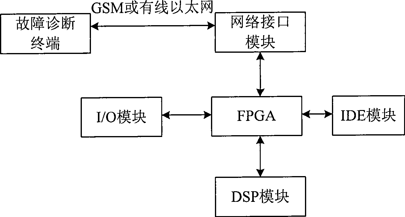
[0056] figure 1 Shown is the hardware structural diagram of the system of the present invention, this car engine fault diagnosis system based on sparse representation, comprises DSP module, IDE module, network interface module, I / O module, FPGA module, described FPGA module is connected with DSP module, The IDE module, the network interface module and the I / O module are connected, the DSP module is connected with the IDE module at the same time, and the network interface module is connected with the fault diagnosis terminal signal.

[0057] The DSP module is used for diagnosing the sound signal of the automobile engine;

[0058] The IDE module stores an engine sound signal fault file database, a signal database to be checked, and a diagnosis result filing database.

[0059] The network interface module is used to receive the sound signal of the automobile engine from the network, and send the diagnosis result;

[0060] The I / O module is used to provide a human-computer inter...


PUM


Abstract

The invention provides an automobile engine fault diagnosing system based on sparse representation, comprising: a DSP module used for operating diagnosis algorithm; an IDE module used for storing a fault file database, a database of signals to be detected and a diagnosis result filing database; a network interface module used for receiving aural signals of the automobile engine coming from the internet, and sending the diagnosis result; an I / O module used for providing a man-machine interaction mechanism; and an FPGA module used for system control and the interface adaptation among all the modules. The automobile engine fault diagnosing method comprises the steps of: preprocessing, sparse decomposition, the feature extraction of the fault file and the signals to be detected, classification algorithm training, fault diagnosis, diagnosis result analysis, the updating of the fault file database and the database of the signals to be detected, stop judgment and diagnosis result output. The system and the method can realize remote diagnosis to the aural signals of the automobile engine, the needed fault file database is small, the diagnosis accuracy is high, the cost is low, and the system is convenient for maintenance and upgrading.

Description

technical field [0001] The invention relates to automobile engine fault diagnosis technology, in particular to an automobile engine fault diagnosis system and method based on sparse representation. Background technique [0002] The sound emitted by an automobile engine during its working process contains a large number of mechanical operating signals. When the engine fails, its vibrating sound and its frequency spectrum will be mutated and distorted. Therefore, by decomposing the sound signal emitted by the engine, the useful signal and the useless signal in the sound signal can be separated, and then the characteristics of the signal can be extracted to detect the running state of the engine and perform fault diagnosis on it. [0003] At present, the fault diagnosis system using the sound signal of the automobile engine is mainly based on the PC, and some are based on the embedded architecture, but the overall structure has not changed. The sound signal of the engine is obt...

Claims


Application Information

Patent Timeline
Patent Type & Authority Applications(China)
IPC IPC(8): G01M15/00
Inventor 吕俊谢胜利杨祖元
Owner SOUTH CHINA UNIV OF TECH
Why Eureka
Try Eureka