
Coaxial synthesizing method for coherent beam

A coherent beam and coaxial technology, applied in optics, optical components, instruments, etc., can solve the problems of laser output power difficulty, beam quality degradation, and output power cannot be greatly improved, achieving high beam combining efficiency and reducing implementation Effects of Difficulty, Broad Applicability

Inactive Publication Date: 2009-03-11
SHANGHAI INST OF OPTICS & FINE MECHANICS CHINESE ACAD OF SCI
View PDF0 Cites 25 Cited by
  • Summary
  • Abstract
  • Description
  • Claims
  • Application Information

AI Technical Summary

Problems solved by technology

However, since various lasers are limited by different mechanisms or conditions, the improvement of their output power is always limited, and the output power of a single laser is inversely proportional to the beam quality
For example, when a solid-state laser is output at high intensity, the nonlinear effect and thermal effect of the gain medium are obviously serious, and the thermally induced birefringence and thermal lens effect will limit the further increase of the output power, and even damage or destroy the gain medium and the output mirror. and other components, while the beam quality degrades
Although some measures are taken to improve this situation, such as using a slab-shaped gain medium, or using traditional traveling wave amplification technology, they cannot completely get rid of the influence of thermal effects in the end, so that the output power cannot be greatly improved.
Another example: fiber laser has the advantages of compact structure, good beam quality and stable output. However, the high-power output system is still limited by the nonlinear effect of doped light, optical damage and thermal effects.
In general, it is quite difficult and expensive to significantly increase the output power of a laser

Method used


Image

  • Coaxial synthesizing method for coherent beam
  • Coaxial synthesizing method for coherent beam
  • Coaxial synthesizing method for coherent beam

Examples


Embodiment Construction

[0033] The present invention will be further described below in conjunction with the embodiments and accompanying drawings, but the protection scope of the present invention should not be limited thereby.

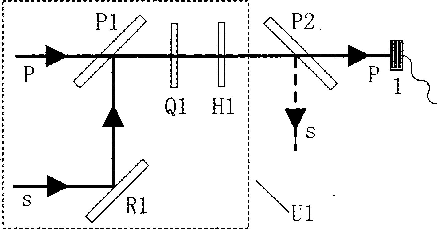
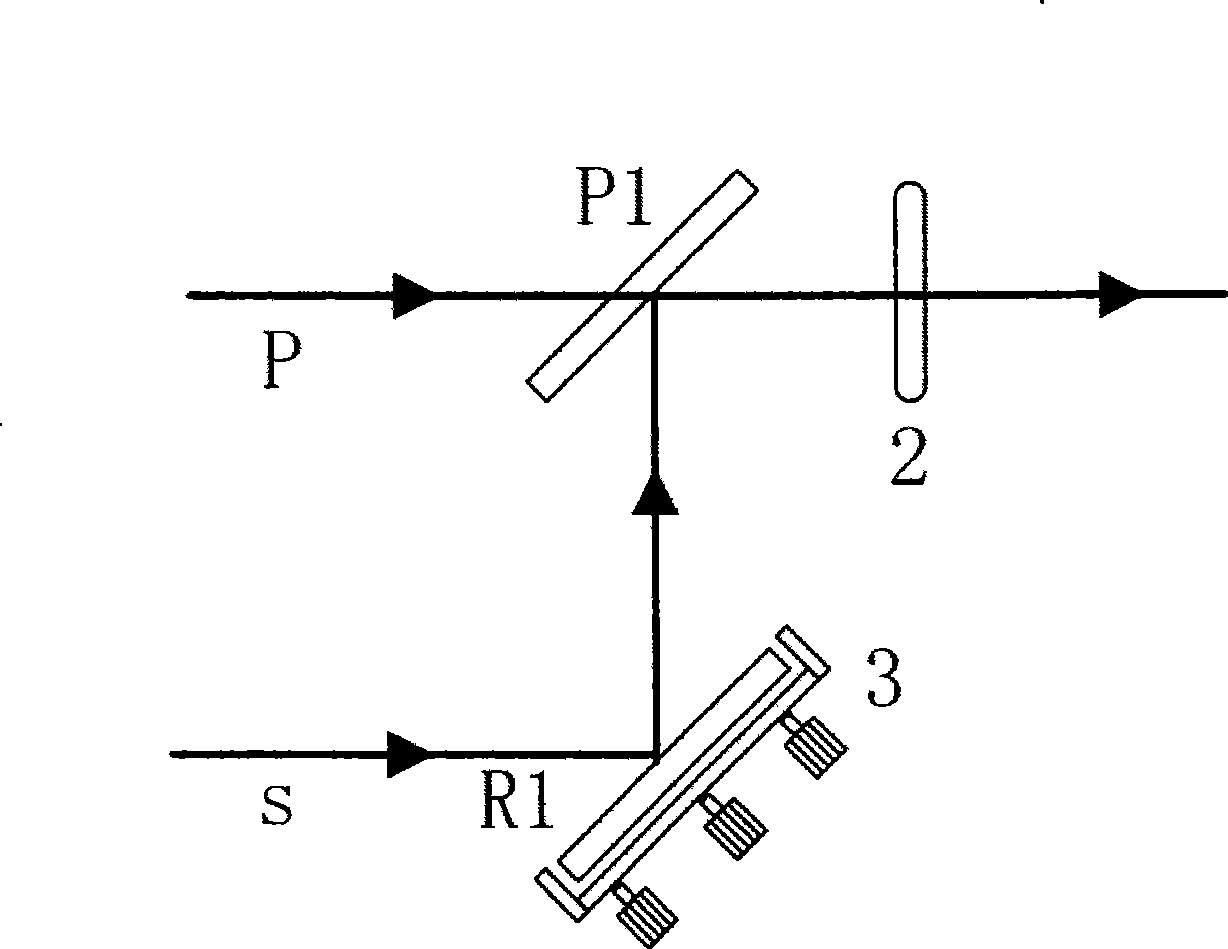
[0034] see first figure 1 , figure 1 It is a schematic diagram of the principle and device of the method for coaxially combining coherent beams of the present invention. It can be seen from the figure that the method for coaxially combining coherent beams of the present invention includes the following steps:

[0035] ① A beam of p-polarized light and a beam of s-polarized light are coaxially combined into a beam of elliptically polarized light through a polarization beam combiner P1;

[0036] ② Then through a 1 / 4 wave plate Q1 and a 1 / 2 wave plate H1, the elliptically polarized light is changed into a beam of s-polarized light or a beam of p-polarized light;

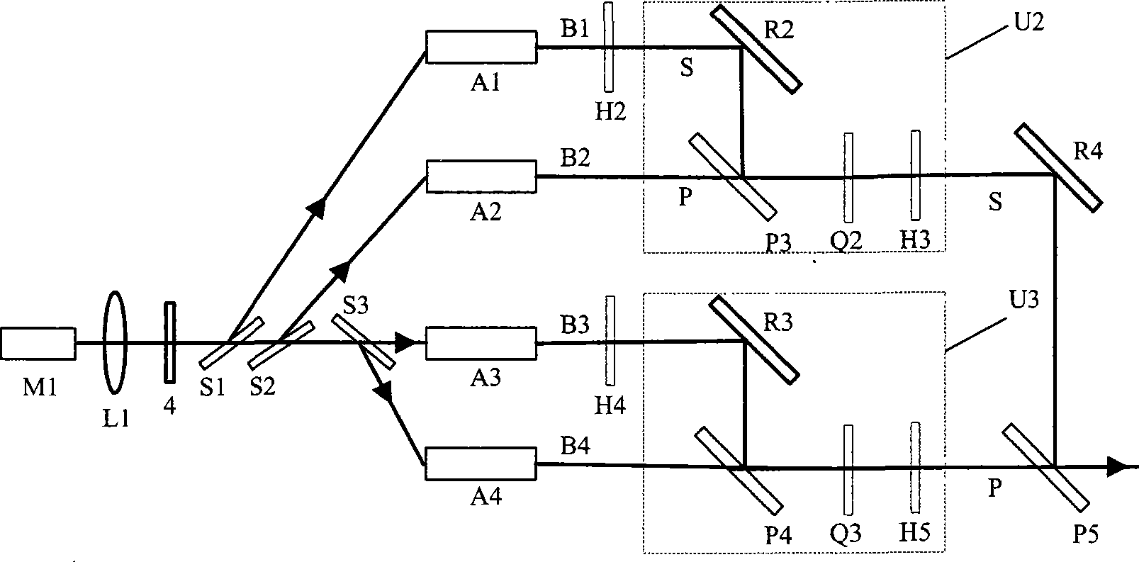
[0037] ③The synthesized s-polarized light or p-polarized light continues to combine with other p-polarized light...


PUM


Abstract

A coaxial combination method for coherent light beams is characterized by including the following steps: 1. a polarized light p and a polarized light s are coaxially combined into an elliptically polarized light through a polarization beam combining mirror; 2. and then the elliptically polarized light is changed into a polarized light s or p through a 1 / 4 wave plate and a 1 / 2 wave plate; and 3. the combined polarized light s or p continues to be combined with other polarized light p or s as the steps 1 and 2, thus achieving the purpose of the coaxial coherent combination of a plurality of laser beams by the adoption of a multi-level combination mode. The invention realizing the combination of a plurality of coherent laser beams is characterized by simple principle, easy realization, high combination efficiency, good beam quality, strong commonality, and the like.

Description

technical field [0001] The present invention is related to laser technology, especially a method for coaxially combining coherent beams to efficiently increase the energy of combined beams and maintain good beam quality. technical background [0002] With the gradual increase in the application of lasers in the fields of national defense, scientific research, and industrial production, the demand for laser beams with high power and high beam quality is becoming increasingly urgent. However, because various lasers are limited by different mechanisms or conditions, the improvement of their output power is always limited, and the output power of a single laser is inversely proportional to the beam quality. For example, when a solid-state laser is output at high intensity, the nonlinear effect and thermal effect of the gain medium are obviously serious, and the thermally induced birefringence and thermal lens effect will limit the further increase of the output power, and even d...

Claims


Application Information

Patent Timeline
IPC IPC(8): G02B27/28G02B27/10G02B7/00
Inventor 董洪成许程肖祁陵邵建达易葵贺洪波范正修
Owner SHANGHAI INST OF OPTICS & FINE MECHANICS CHINESE ACAD OF SCI
Learn More