Optical film auto-assembling system and optical film auto-assembling method

An optical film, automatic assembly technology, applied in chemical instruments and methods, optics, optical components, etc., can solve problems such as poor optical film assembly, improve assembly quality, and avoid scratches and pressure injuries.

Active Publication Date: 2009-03-11
INNOCOM TECH SHENZHEN +1
View PDF0 Cites 8 Cited by
  • Summary
  • Abstract
  • Description
  • Claims
  • Application Information

AI Technical Summary

Problems solved by technology

[0009] In order to solve the problem of poor assembly of optical films in the prior art, it is necessary to provide an automatic assembly system for optical films with better assembly effect

Method used


Image

  • Optical film auto-assembling system and optical film auto-assembling method
  • Optical film auto-assembling system and optical film auto-assembling method
  • Optical film auto-assembling system and optical film auto-assembling method

Examples


Embodiment Construction

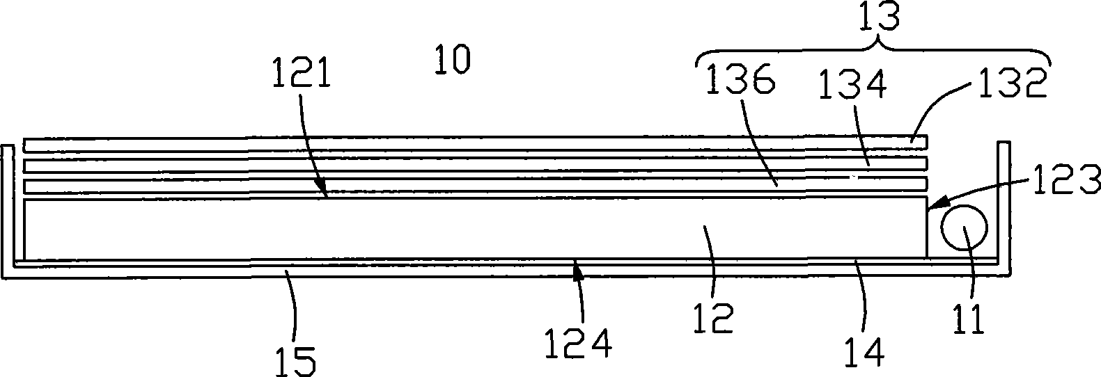
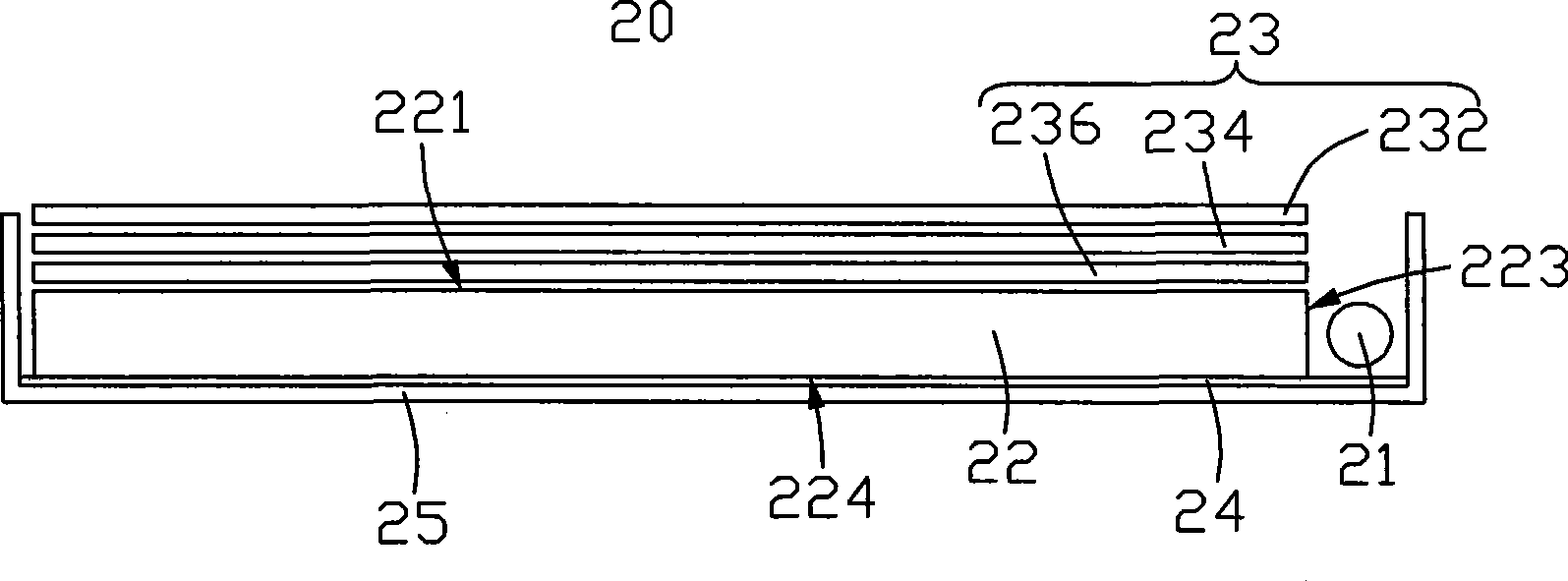
[0018] see figure 2 , is a schematic diagram of a backlight module. The backlight module 20 includes a light source 21 , a light guide plate 22 , an optical film set 23 , a reflection sheet 24 and a frame 25 . The frame 25 accommodates the light guide plate 22 , the optical film set 23 and the reflection sheet 24 .

[0019] The light guide plate 22 includes a light emitting surface 221 , a bottom surface 224 opposite to the light emitting surface 221 , and a light incident surface 223 intersecting the light emitting surface 221 and the bottom surface 224 .

[0020] The optical film set 23 includes an upper diffusion sheet 232, a brightness enhancement sheet 234, and a lower diffusion sheet 236, and the lower diffusion sheet 236, the brightness enhancement sheet 234, and the upper diffusion sheet 232 are sequentially stacked on the light output of the light guide plate 22 from bottom to top. Face 221.

[0021] The assembly method of the backlight module 20 includes the foll...


PUM


Abstract

The invention relates to an optical mask automatic assembly system and an optical mask automatic assembly method. The optical mask automatic assembly system comprises a transmission device, an automatic dyestripping device and a modularity device; the transmission device can transmit an optical mask to go through dyestripping along a preset direction, the automatic dyestripping device carries out automatic dyestripping treatment over the optical mask passing through and the modularity device can carry out modularity assembly to the dyestripped optical mask and other optical mask to go through modularity.

Description

technical field [0001] The invention relates to an automatic assembly system for an optical film and an automatic assembly method for an optical film. Background technique [0002] At present, liquid crystal displays are gradually replacing traditional cathode ray tube (Cathode Ray Tube, CRT) displays used in computers, and because liquid crystal displays are light, thin, and small, they are very suitable for use in desktop computers and laptops. In portable computers, personal digital assistants (Personal Digital Assistant, PDA), portable phones, televisions and a variety of office automation and audio-visual equipment. [0003] Since the liquid crystal panel is a non-self-luminous display device, in order to achieve the display purpose, it is necessary to provide a light source device for the liquid crystal panel to realize its display function, such as a backlight module, whose function is to provide the liquid crystal panel with sufficient brightness and uniform distribu...

Claims


Application Information

Patent Timeline
Patent Type & Authority Applications(China)
IPC IPC(8): G02F1/13357G02B7/00B25H1/00B32B38/10B32B33/00G02F1/1335
Inventor 岳军
Owner INNOCOM TECH SHENZHEN
Why Eureka
Try Eureka