Method for continuously non-interrupt numerical control processing for plate parts

A technology for processing plates and parts, which is applied in the field of continuous and uninterrupted CNC processing of plate-shaped parts, can solve the problems of easy safety accidents and affect processing efficiency, and achieve the effects of simple operation, improved cutting conditions, easy operation and programming

Active Publication Date: 2010-06-09
CHENGDU AIRCRAFT INDUSTRY GROUP
View PDF1 Cites 3 Cited by
  • Summary
  • Abstract
  • Description
  • Claims
  • Application Information

AI Technical Summary

Problems solved by technology

[0003] The task of the present invention is to provide a method for continuous and uninterrupted CNC machining plate-shaped parts to solve the problem that during the CNC machining process, the tool collides with the pressure plate. It is easy to cause safety accidents and affect the processing efficiency and processing quality.

Method used


Image

  • Method for continuously non-interrupt numerical control processing for plate parts
  • Method for continuously non-interrupt numerical control processing for plate parts

Examples


Embodiment Construction

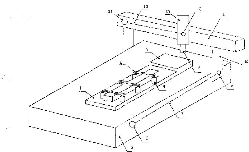
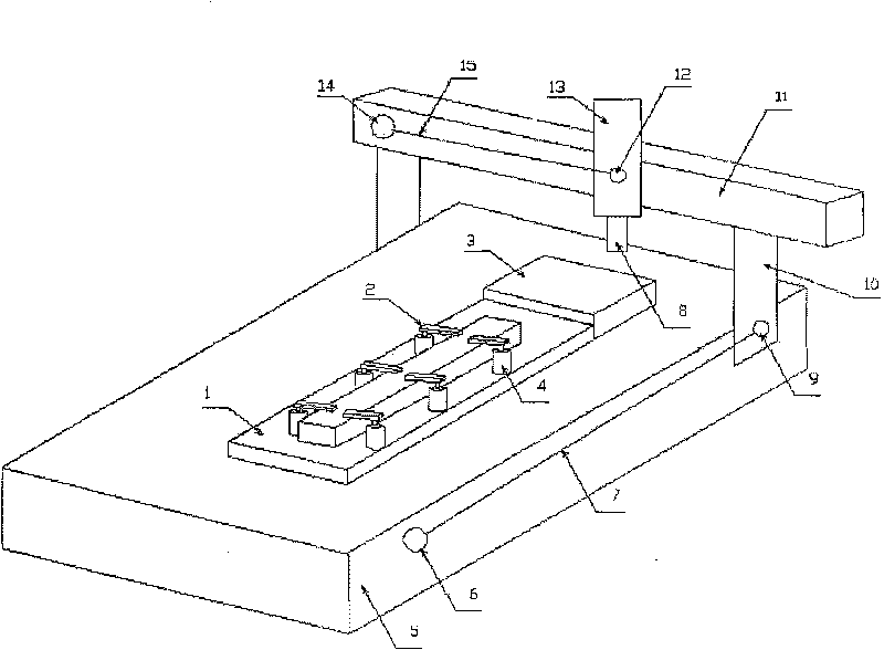
[0013] refer to figure 1 . According to the present invention, the whole control process is divided into three steps.

[0014] Step 1: Detect and track the position of the tool by the wire displacement sensor. Choose a safe location and attach the wire displacement sensor to a place where the machine tool does not move. The stay wire displacement sensors 6 and 14 are respectively adsorbed by two controllable permanent magnet bases (not shown) fixed on the side of the X-axis table 5 and on the Y-axis beam. The stay wire ends (9, 12) of the stay wire displacement sensor are respectively fixed on the moving column (10) of the X axis and the moving slide table of the Y axis. The displacement sensors (6, 14) and the stay wire ends (9, 12) are respectively connected together by the stay wires (7, 15). The controllable permanent magnet base adsorbs the two pull wire displacement sensors (6) and (14) on the X and Y axes of the numerically controlled machine tool. The control syst...


PUM


Abstract

The invention discloses a continuous digital control method for processing a plate part. A displacement signal of a displacement sensor with pulling thread is fed back to a control system of a follow-up clamp; a teaching method is used for remembering the coordinate position of an anti-collision press plate; the control system of the follow-up clamp is used for collecting the displacement signal of the displacement sensor with pulling thread in real time; and the forward movement range of the press plate on the clamp for avoiding the collision with a digital control cutting tool is calculatedand analyzed according to the length of the press plate on the follow-up clamp; the press plate on the clamp is controlled to avoid collision and be compressed automatically; and an anti-collision control command or a clamping command is initiated to a press plate executing mechanism. In the method, the displacement sensor with pulling thread is utilized to collect the coordinate position of the press plate for avoiding the collision with the digital control cutting tool; the teaching method is adopted to cause the cutting tool to be moved within the forward movement range of the press plate for avoiding the collision with the digital cutting tool; the control system is used for controlling the press plate executing mechanism on the clamp to cause the press plate to avoid collision automatically. The method solves the problem that safety accidents easily occur and processing efficiency and processing quality are affected since running stop and manual disassembling the press plate on the clamp are required when the digital control cutting tool collides with the press plate.

Description

technical field [0001] The invention relates to a method for continuous and uninterrupted numerical control machining of plate-shaped parts. Background technique [0002] In the CNC machining process, especially the CNC machining of large and medium-sized plate-shaped parts, it is currently necessary to use a pressure plate to clamp and fix the parts on the machine tool table or fixture. In order to prevent the tool from colliding with the pressure plate, when the tool moves to the vicinity of the pressure plate, the machine tool must stop processing, lift the tool to avoid the fixture, change the tool feed, tool retract, avoidance point, tool selection, processing method selection, tool path selection, and spare part machining. This is the traditional processing method of the so-called "knife to platen (fixture)". In this process, the tool path avoids the fixture area by specifying the avoid area (Avoid Areas), and changing the 2-axis or 2.5-axis CNC rough milling and fini...

Claims


Application Information

Patent Timeline
Patent Type & Authority Patents(China)
IPC IPC(8): G05B19/406B23Q17/22
Inventor 李国进周文强
Owner CHENGDU AIRCRAFT INDUSTRY GROUP
Why Eureka
Try Eureka