
Device and method for terminal charger charging, USB charging and data communication

A technology of charger and USB interface, applied in the field of communication electronics, can solve the problems of signal integrity damage, USB2.0 interface communication reliability reduction, etc. simple effect

Active Publication Date: 2009-03-11
LEADCORE TECH
View PDF0 Cites 59 Cited by
  • Summary
  • Abstract
  • Description
  • Claims
  • Application Information

AI Technical Summary

Problems solved by technology

[0012] In the case that the amount of data transmission between the terminal and external devices is not large, most terminal manufacturers can only provide USB1.1 interface for communication between the terminal and the outside. The data transmission rate of the USB1.1 interface is up to 12Mbps. For data transmission, the requirements for signal quality are not very strict. However, with the increasing multimedia functions and data processing functions of the terminal, the requirements for data throughput rate are increasing day by day. USB2.0 interface, because the USB2.0 interface will greatly improve the requirements for circuit signal quality, thus putting forward higher requirements for ensuring signal integrity in USB circuit design, and the existing USB circuit design is directly in the management of USB communication. The data lines where the pins D+ and D- are located add loads such as resistance, inductance and capacitance in parallel, causing damage to the signal integrity with a transmission rate of up to 480Mbps, and greatly reducing the reliability of USB2.0 interface communication

Method used


Image

  • Device and method for terminal charger charging, USB charging and data communication
  • Device and method for terminal charger charging, USB charging and data communication
  • Device and method for terminal charger charging, USB charging and data communication

Examples


Embodiment Construction

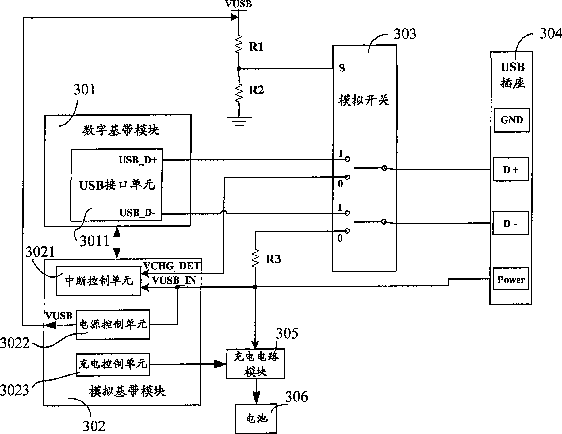
[0051] image 3 A three-in-one device structure diagram for terminal charger charging, USB charging and data communication in the present invention, including:

[0052] The digital baseband module 301, the USB interface module 3011 in this module includes pins USB_D+ and USB_D-, the pin USB_D+ is connected to the No. 1 output end of the first switch of the analog switch 303, and the pin USB_D- is connected to the second output end of the analog switch 303. Connect to output 1 of the switch.

[0053] An analog baseband module 302, which includes pins VCHG_DET, VUSB_IN and VUSB, wherein the pin VCHG_DET is connected to the No. 0 output end of the first switch of the analog switch 303, and the pin VUSB_IN is connected to the No. 0 output end of the second switch of the analog switch 303. output connection.

[0054] The module also includes an interruption control unit 3021, a power supply control unit 3022 and a charging control unit 3023, wherein,

[0055] The pin VCHG_DET is...


PUM


Abstract

The invention discloses a method for terminal charger charge, USB charge and data communication. The method includes the steps that a processor detects the triggering condition that the USB insertion interrupts and the charger insertion interrupts, if both interrupts are triggered, a charger is confirmed to be inserted in the terminal, and the charger charge process starts; if the condition that only the USB insertion interrupts is triggered, the condition that a USB data wire is inserted in the terminal is confirmed, the USB charge process starts, and USB data transmission is carried out. Meanwhile, the invention discloses a device for terminal charger charge, USB charge and data communication, which comprises a processor, a USB interface module and a selecting module, wherein the selecting module comprises a selecting end and two single input and double output switches. The invention provides users with a solution proposal that has the advantages of simple circuit structure, small resource occupation and great improvements of signal quality and data transmission reliability and integrates the functions of terminal charger charge, USB charge and data communication into a whole.

Description

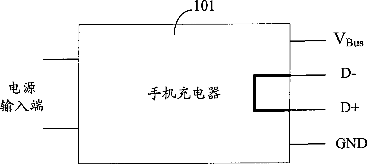
technical field [0001] The invention mainly relates to the field of communication electronics, in particular to a device and method for terminal charger charging, USB charging and data communication. Background technique [0002] In 2007, the country promulgated the "Mobile Communication Handset Charger and Interface Technical Requirements and Test Methods", which clearly stipulates that the interface between the cable and the plug of the terminal charger must use a USB interface, and the internal tube of the USB interface in the charger The pins D+ and D- are short-circuited, and the connection cable and interface between the charger and the terminal are designed by the designer himself. [0003] figure 1 It is a schematic diagram of the USB interface of the terminal charger 101 under the existing standard, figure 1 Among them, the two pins on the left of the terminal charger 101 are power input terminals, and the four pins on the right are respectively V Bus , D+, D- an...

Claims


Application Information

Patent Timeline
Patent Type & Authority Applications(China)
IPC IPC(8): H04B1/40H04Q7/32
Inventor 黄忠王海龙林俊超
Owner LEADCORE TECH
Learn More