Suppressing vibration method for marine riser vortex-induced vibration and suppressing vibration apparatus thereof

A vortex-induced vibration and riser technology, which is applied in the directions of support devices, drill pipes, casings, etc., can solve the problems of large effective cross-section in the incoming flow direction, adhesion of marine sediments, and large amount of materials, so as to achieve difficult adhesion of marine sediments. , Reduce the project cost, reduce the effect of vortex-induced vibration

Inactive Publication Date: 2009-03-18
OCEAN UNIV OF CHINA
View PDF0 Cites 39 Cited by
  • Summary
  • Abstract
  • Description
  • Claims
  • Application Information

AI Technical Summary

Problems solved by technology

However, the above-mentioned anti-vibration device also has the following problems: relative weight is large, material consumption is large; the effective cross-section in the direction of incoming flow is large; marine sediments are easy to adhere to, etc.

Method used


Image

  • Suppressing vibration method for marine riser vortex-induced vibration and suppressing vibration apparatus thereof
  • Suppressing vibration method for marine riser vortex-induced vibration and suppressing vibration apparatus thereof
  • Suppressing vibration method for marine riser vortex-induced vibration and suppressing vibration apparatus thereof

Examples


Embodiment 1

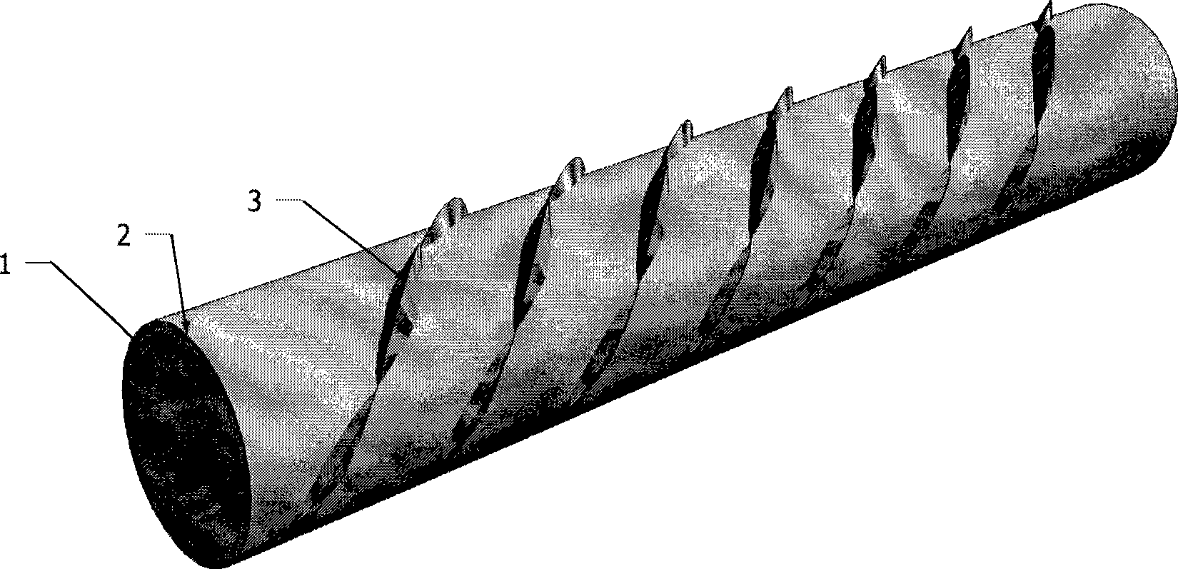
[0027] Such as figure 1 , A spiral spoiler rib layout: the outer diameter of the riser D=1m, and the spiral position is marked on the outer surface of the deflector 2 with a pitch of 5m. The length Y of the spoiler rib 4 is 0.5 meters, the thickness Z of the middle part of the rib bottom is 0.3 meters, and the rib height H is 0.3 meters. Install the spoiler ribs on the riser along the spiral position, and the distance between two adjacent spoiler ribs is 5 meters.

Embodiment 2

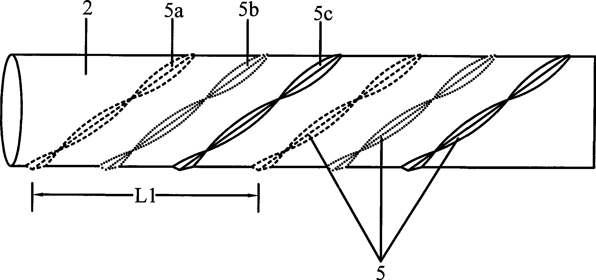
[0029] Such as figure 2 , In the form of three spiral spoiler ribs: the outer diameter of the riser D=1m, the spiral position is marked on the outer surface of the deflector 2 according to the pitch L1 of 5m, which is the arrangement position of the first spoiler rib 5a ; Based on the first spiral, the second spiral is wound in parallel with the first spiral at a distance of 1.67 meters. This is the location of the second spoiler rib 5b; and then the second spiral As a benchmark, the third spiral is wound in parallel with the second spiral at a distance of 1.67 meters, which is the location of the third spoiler rib 5c. The length Y of the spoiler ribs 5a, 5b, and 5c is 0.5 meters, the thickness Z of the middle part of the rib bottom is 0.3 meters, and the rib height H is 0.3 meters. The three spoiler ribs are simultaneously wound along the spiral position and fixedly installed on the riser. The distance between two adjacent spoiler ribs is 1.67 meters in a pitch L1.

Embodiment 3

[0031] Such as figure 2 , In the form of three spiral spoiler ribs: the outer diameter of the riser D=1m, the spiral position is marked on the outer surface of the deflector 2 according to the pitch L1 of 9m, which is the arrangement position of the first spoiler rib 5a ; Based on the first spiral, the second spiral is wound in parallel with the first spiral at a distance of 3.0 meters. This is the location of the second spoiler rib 5b; and then the second spiral As a benchmark, the third spiral is wound in parallel with the second spiral at a distance of 3.0 meters. This is the arrangement position of the third spoiler rib 5c; the length Y of the spoiler ribs 5a, 5b, and 5c are all 0.5 M, the thickness Z of the middle part of the rib bottom is 0.3 m, and the height H of the rib is 0.3 m. Three spoiler ribs are installed on the riser along the spiral line at the same time, and the distance between two adjacent spoiler ribs is 3.0 meters within a pitch of L1.


PUM


Abstract

The invention relates to a vibration inhibiting method and a vibration inhibiting device capable of effectively inhibiting vortex-induced vibration of a marine riser. The vibration inhibiting device is provided with the riser, an air guide sleeve on the riser, and a flow disturbing device which is fixed on the air guide sleeve, and is characterized in that the flow disturbing device is a flow disturbing rib which is formed by a plurality of end-to-end crescent-shaped flow disturbing ribs; and the flow disturbing rib is arranged on the outer surface of the air guide sleeve in the form of being winded by a spiral line, and the screw pitch of the flow distributing rib is 5 to 15 times of the outside diameter of the riser. The vibration inhibiting method comprises the following steps: firstly, the air guide sleeve which is enwrapped and fixed on the outer surface of the riser is prepared according to the outside diameter of the riser required to be protected; secondly, one flow disturbing rib or a plurality of flow disturbing ribs which are manufactured are fixed on the outer surface of the air guide sleeve in advance according to the screw pitch or the position of the spiral line which is predefined and marked on the outer surface of the air guide sleeve; and thirdly, the air guide sleeve provided with the flow disturbing rib is arranged on the outer surface of the riser. Therefore, the vibration inhibiting method and the vibration inhibiting device can effectively inhibit the vortex-induced vibration of the riser; the weight of the device can be reduced from 30 percent to 60 percent; and the construction cost can be greatly reduced.

Description

Technical field [0001] The invention belongs to the technical field of laying of marine riser facilities, and specifically relates to a vibration suppression method and a vibration suppression device capable of effectively suppressing the vortex-induced vibration of the marine riser. Background technique [0002] The marine riser is the main connecting piece between the offshore platform and the subsea wellhead. As a connection channel between the sea surface and the seabed, it can be used for floating offshore platforms, fixed platforms and drilling ships. When the ocean current flows through the elongated cylindrical body with a smooth surface, under a certain flow rate condition, strong vortices alternately form on both sides of the cylindrical body. The shedding of the vortex will produce a periodic variable force on the riser, making the vertical The tube vibrates laterally in the direction perpendicular to the flow direction; the vibration of the structure in turn has an ef...

Claims


Application Information

Patent Timeline
Patent Type & Authority Applications(China)
IPC IPC(8): E21B17/10E21B15/02F16L55/04
Inventor 郭海燕刘晓春张永波王海青
Owner OCEAN UNIV OF CHINA
Why Eureka
Try Eureka