

Pfo closing device
A technology of closing device and foramen ovale, which is applied in medical science, heating surgical instruments, surgical forceps, etc., can solve the problems of size limitation of medical instruments, and achieve reliable puncture operation or connection operation and accurate operation process
- Summary
- Abstract
- Description
- Claims
- Application Information
AI Technical Summary
Problems solved by technology
Method used
Image

Examples
no. 1 approach
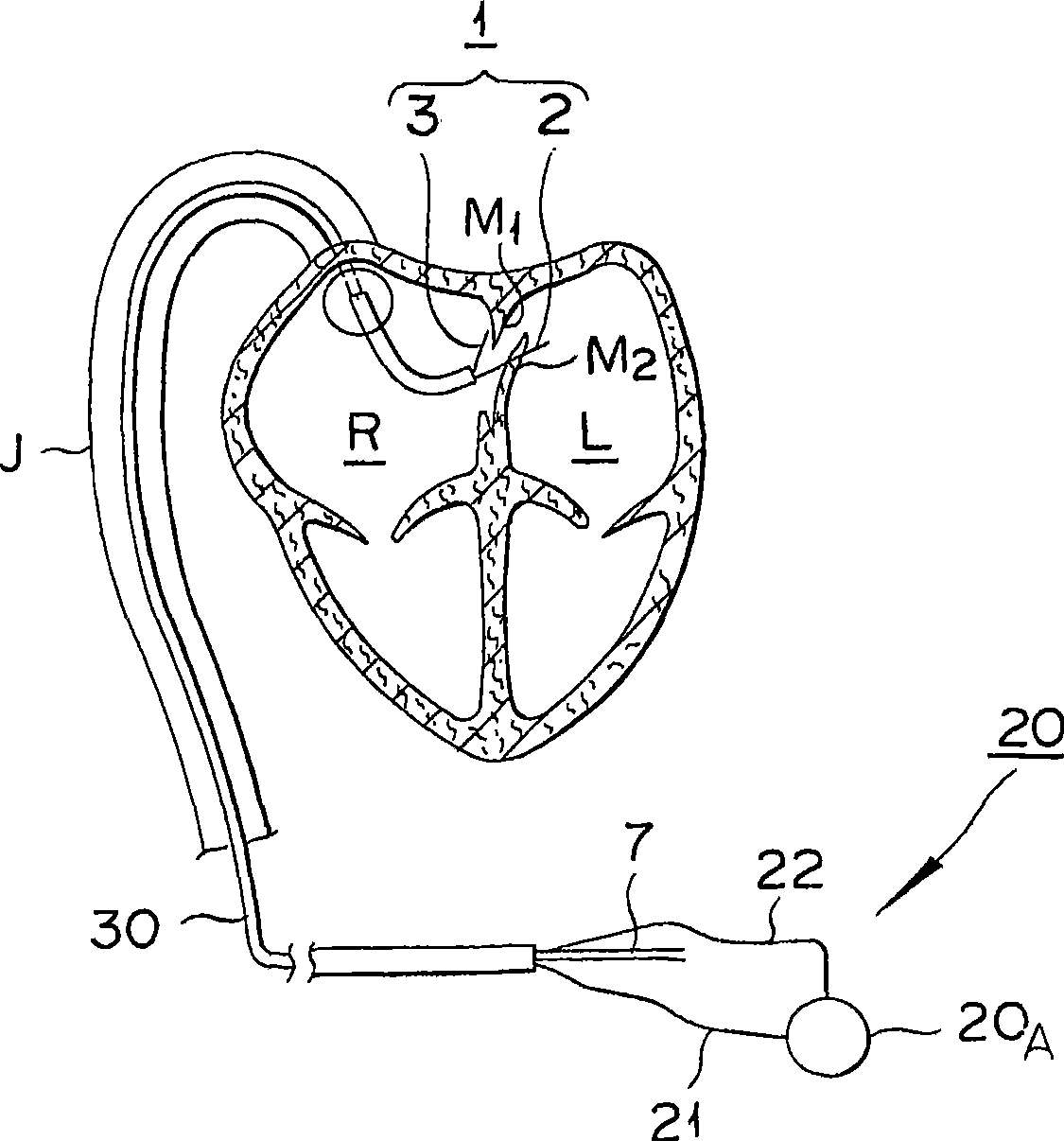
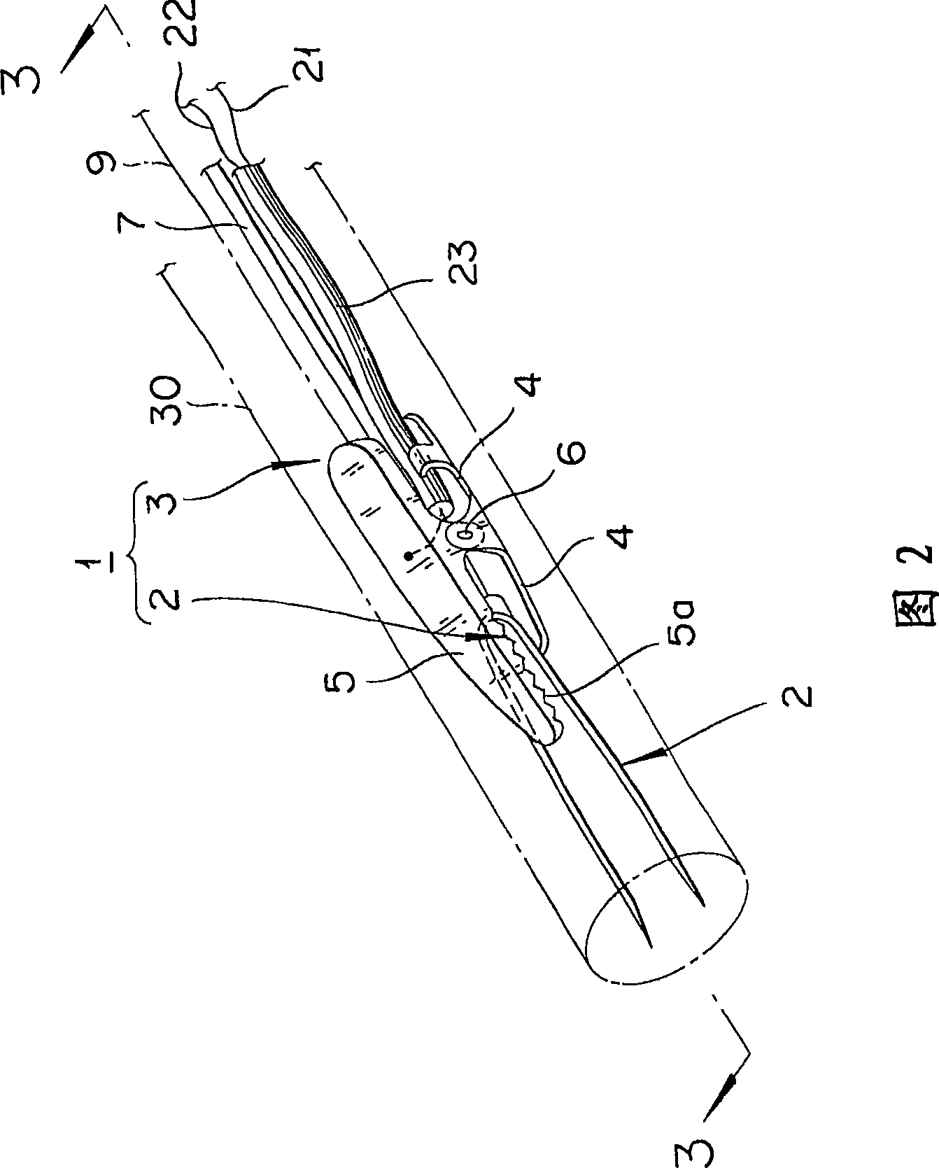
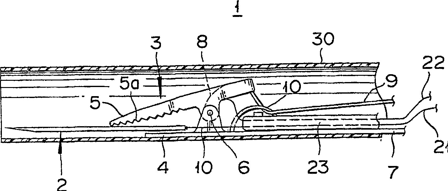
[0060] figure 1 is a schematic cross-sectional view showing the use of the PFO closure device according to the first embodiment of the present invention, FIG. 2 is an enlarged perspective view of a main part of the first embodiment, and image 3 is a cross-sectional view taken along line 3-3 of FIG. 2 .
[0061] Such as figure 1 As shown, the PFO closure device according to this embodiment generally includes a clamping device 1 and an energy supply device 20, wherein the clamping device 1 is used to clamp SP M2 and SS M1, and the energy supply device 20 is used to supply energy to connect Tissue clamped by the clamping device 1 . The clamp device 1 is installed at the distal end (tip) of the percutaneous catheter 30, capable of extending and retracting (moving forward and backward). In use, the clamping device 1 is inserted into the inferior vena cava J fully stored in the catheter 30 . During execution, the clamping device 1 is extended from the distal end of the catheter...
no. 2 approach
[0081] Figure 6 is a schematic perspective view of a PFO closure device according to a second embodiment of the present invention, Figure 7 is an enlarged sectional view of the main part showing the storage of the PFO closure, Figure 8 is a schematic cross-sectional view showing a situation where the clamping member is in contact with the guide catheter, and Figure 9 is a schematic cross-sectional view showing a state where the clamping member is pushed by the guide catheter. Incidentally, in the following description, members that are the same as those described above are denoted by the same reference numerals as those described above, and descriptions of these members are omitted.
[0082] The use of the PFO closure device according to the present embodiment is preferred because the clamp device 1 can be stored more compactly in the catheter 30 .
[0083] Such as Figure 6 As shown, the PFO closure device in this embodiment generally includes a guide catheter 31, a c...
no. 3 approach
[0098] Fig. 10 is a schematic perspective view showing a third embodiment of the present invention, Figure 11 is the front view of the support, Figure 12 is a side view of the third embodiment, Figure 13 is a plan view of the third embodiment, and Figure 14 is a side view of the main part, showing the state when clamped in the third embodiment.
[0099] In this embodiment, a multi-lumen support part 50 is provided at the distal end (tip) of the catheter 30, and the needle part 2, the clamp member 3B, the positioning device 40, etc. respectively pass through the lumens in the support part 50, thereby achieving Compact and smooth operation.
[0100] As shown in FIG. 10 , the device includes a support portion 50 fixedly positioned in the catheter 30 at the distal end. Such as Figure 11As shown, the support portion 50 has five lumens opened therein, and the needle portion 2 passes through the first and second lumens L1 and L2 and is positionally fixedly connected to the ...
PUM
 Abstract
Description
Claims
Application Information