Phosphor for display and field emission display

A display device and field emission technology, applied in the direction of image/graphic display tubes, luminescent materials, cathode ray tubes/electron beam tubes, etc., can solve the problems of not being able to directly use phosphors, etc., and achieve good display characteristics and high luminescence The effect of brightness and long life

Inactive Publication Date: 2009-03-18
CANON KK
View PDF1 Cites 4 Cited by
  • Summary
  • Abstract
  • Description
  • Claims
  • Application Information

AI Technical Summary

Problems solved by technology

[0006] However, in FEDs having an excitation voltage of 5 to 15 kV, it is considered that the above-mentioned phosphors cannot be used as they are. In order to improve the luminous properties of FED itself, it is also desired to develop phosphors for FEDs with excellent luminous properties.

Method used


Image

  • Phosphor for display and field emission display
  • Phosphor for display and field emission display
  • Phosphor for display and field emission display

Examples


Embodiment 1

[0042] The raw material containing the element or the compound containing the element which constitutes the matrix of a phosphor and an activator is weighed, and it becomes the composition shown in Table 1 (SrGa 2 S 4 : The stoichiometric ratio of Eu containing ratio 2 mol %) is fully mixed. A quartz crucible was filled with the phosphor material obtained by adding an appropriate amount of sulfur and activated carbon, and fired in a hydrogen sulfide atmosphere. The firing conditions were 800° C.×60 minutes.

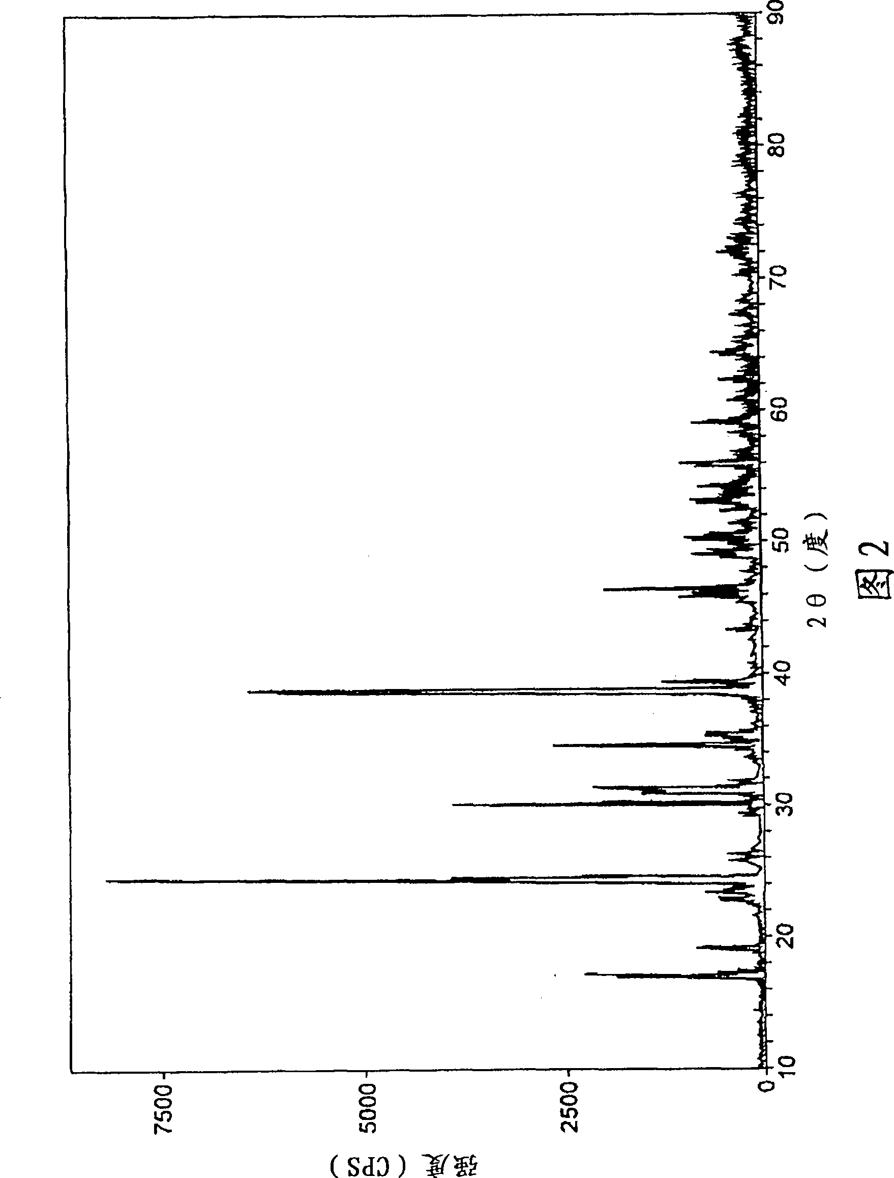
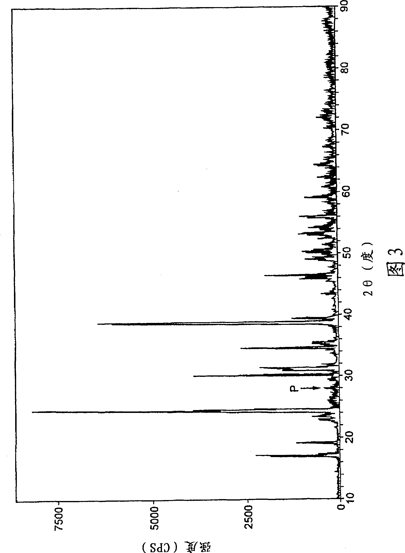
[0043] Then, the obtained burnt product was washed with water and dried, and then sieved to obtain europium (Eu) activated strontium thiogallate phosphor (SrGa 2 S 4 : Eu). As a result of measuring the XRD (X-ray diffraction) spectrum of the europium-activated strontium thiogallate phosphor, the XRD (X-ray diffraction) pattern shown in FIG. 2 was obtained. There is no peak in the range of 27 to 29° at the diffraction angle (2θ) of the XRD pattern, confirming that the...

Embodiment 2

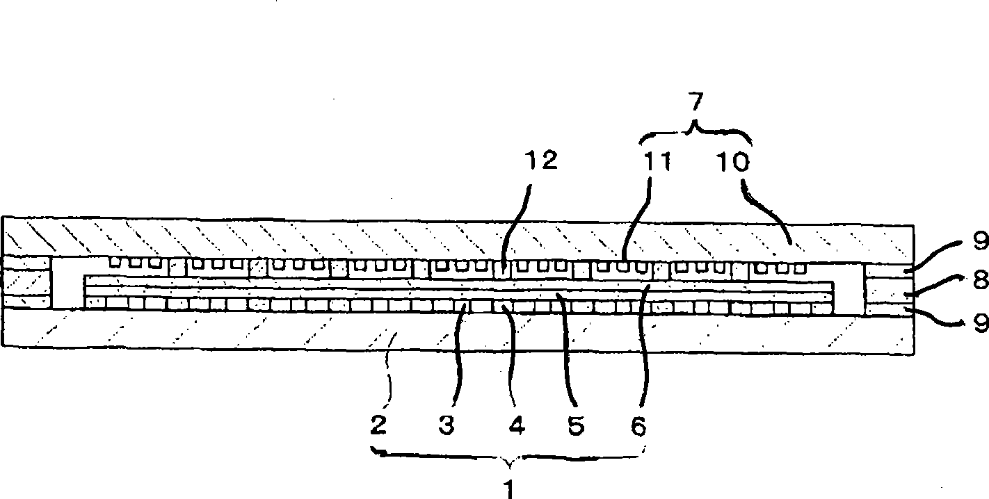
[0052] The europium (Eu) prepared in Example 1 was used to activate the strontium thiogallate phosphor (SrGa 2 S 4 :Eu) with the known blue emitting phosphor (ZnS:Ag, A1) and red emitting phosphor (Y 2 o 2 S:Eu), forming a phosphor layer on a glass substrate to become a panel. While assembling this panel and a rear panel having a plurality of electron emission elements through a support frame, the gaps between them were hermetically sealed while being evacuated. The FED produced in this way was confirmed to be excellent in color reproducibility represented by emission luminance, and also exhibited good luminance characteristics even after being driven for 1000 hours under normal temperature and rated operation.


PUM

PropertyMeasurementUnit
thicknessaaaaaaaaaa
thicknessaaaaaaaaaa

Abstract

Disclosed is a phosphor for displays which is characterized by being composed of a europium-activated thiogallate phosphor represented by the following chemical formula: SrGa2S4:Eu. This phosphor is also characterized by containing no gallium sulfide (Ga2S3) and being a green phosphor which emits light when excited by an electron beam having an accelerating voltage of 5-15 kV. Consequently, this invention provides a phosphor for displays having high luminance, which emits light when excited by a pulse electron beam having an accelerating voltage of 5-15 kV.

Description

technical field [0001] The present invention relates to a phosphor for a display device and a field emission display device using the same. Background technique [0002] With the advent of the multimedia era, display devices, which are the core equipment of digital networks, are required to have larger screens, higher resolution, adaptability to various information sources such as computers, and the like. [0003] Among the display devices, field emission display devices (Field Emission Display: FED) using electron emission elements such as field emission cold cathode elements are used as large-screen and thin displays that can display various information in a dense and high-definition manner. In recent years, digital devices have been actively researched and developed. [0004] The basic display principle of the FED is the same as that of a cathode ray tube (CRT). Electron rays are used to excite phosphors to make them emit light. However, the acceleration voltage (excitat...

Claims


Application Information

Patent Timeline
Patent Type & Authority Applications(China)
IPC IPC(8): C09K11/62C09K11/08H01J29/20H01J31/12
CPCH01J29/20H01J31/123C09K11/7731
Inventor 横泽信幸山口研一
Owner CANON KK
Why Eureka
Try Eureka