Core catcher and its manufacturing method, and reactor container and its modifying method

A technology for a nuclear reactor and a manufacturing method, which is applied in the fields of reactors, nuclear engineering, nuclear power generation, etc., can solve problems such as difficulties in the structural design of storage containers, and achieve the effect of improving efficiency

Active Publication Date: 2009-03-18
KK TOSHIBA
View PDF5 Cites 11 Cited by
  • Summary
  • Abstract
  • Description
  • Claims
  • Application Information

AI Technical Summary

Problems solved by technology

However, it is difficult to ensure a large enough floor area in the design of the storage container structure

Method used


Image

  • Core catcher and its manufacturing method, and reactor container and its modifying method
  • Core catcher and its manufacturing method, and reactor container and its modifying method
  • Core catcher and its manufacturing method, and reactor container and its modifying method

Examples


no. 1 Embodiment approach

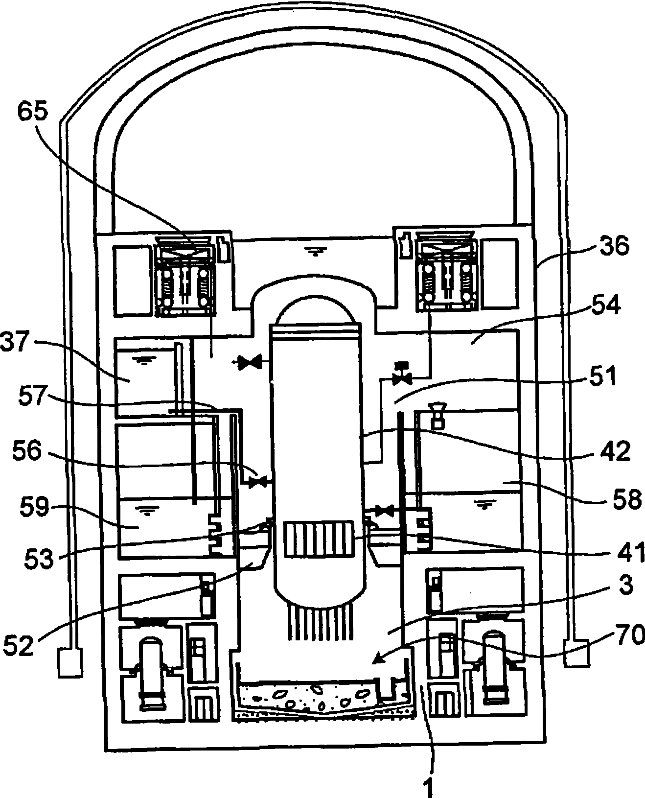
[0068] image 3 It is a longitudinal sectional view of the nuclear reactor casing according to the first embodiment of the present invention.

[0069] Inside the nuclear reactor casing 36 there is a space called a dry well 51 in which a nuclear reactor pressure vessel (RPV) 42 is disposed. The nuclear reactor pressure vessel 42 is fixed by the RPV support portion 52 via the RPV hem portion 53 . The space above the RPV support portion 52 of the dry well 51 is referred to as an upper dry well 54 , and the space below is referred to as a lower dry well 3 . In addition, the wall surrounding the lower dry well 3 is called a foundation side wall 1 . In the ESBWR, the RPV support portion 52 is supported by the foundation side wall 1 .

[0070] The core 41 is housed inside a nuclear reactor pressure vessel 42 .

[0071] In the upper dry well 54, a gravity-fall core cooling system (GDCS) pool 37 is provided. The GDCS pool 37 is connected to the nuclear reactor pressure vessel 42 t...

no. 2 Embodiment approach

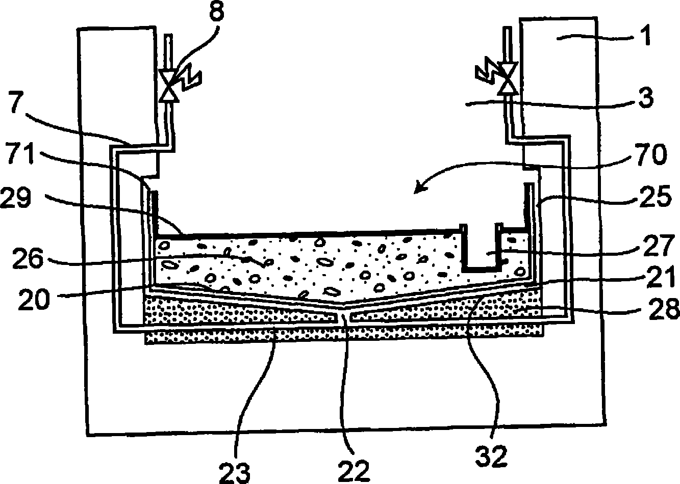
[0104] The core collector according to the second embodiment of the present invention uses a combination of a plurality of subdivided main body segments 30 for easy installation.

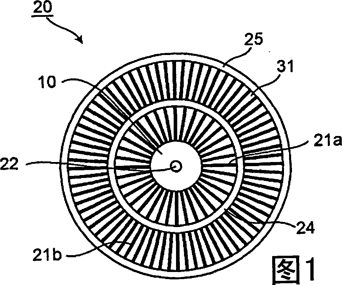
[0105] Figure 4 It is a perspective view of the main body section 30 and the bottom cover 32 of the second embodiment. Figure 5 It is a bottom view of the main body segment 30 of the second embodiment.

[0106] Cooling fins 31 are formed on the lower surface of the body segment 30 . A bottom cover 32 having the same projected shape as the main body segment 30 is installed under the cooling fins 31 , and between the cooling fins 31 is a cooling channel 21 through which cooling water passes.

[0107] The main body piece 30 and the cooling fins 31 integrally formed with the main body piece 30 are made of steel, for example, and the overall thickness is about 18 cm. In addition, the thickness of the bottom cover is, for example, about 2 cm, and the thickness of the main body piece 30 as a whole is ...

no. 3 Embodiment approach

[0115] Figure 8 It is an elevational cross-sectional view of a nuclear reactor casing according to a third embodiment of the present invention.

[0116] In the nuclear reactor casing 102 , the foundation 115 is formed by the foundation floor 107 located in the lower part and the cylindrical foundation side wall 124 surrounding the periphery. The nuclear reactor pressure vessel 101 containing the core 123 is supported by the base side wall 124 .

[0117] In addition, a containment pool 104 is formed in the lower portion of the nuclear reactor casing 102 so as to surround a base side wall 124 . Water is stored in the suppression tank 104 .

[0118]A molten core cooling device (core collector) 130 is arranged on the foundation ground 107 . The water injection pipe 108 is connected to the molten core cooling device 130 . In addition, the water injection pipe 108 is connected to the water tank 105 located in the upper part of the nuclear reactor casing 102 via the injection va...


PUM


Abstract

The invention relates to a core catcher and its manufacturing method, and an reactor container and its manufacturing method, to improve the efficiency for cooling the core debris, which is produced when the core in a reactor container melts and flows through the reactor container. The core debris, which is produced when the core in the reactor container melts and flows through the reactor container, is caught by a core catcher including a steel body (20), which is positioned below the reactor container and provided with cooling channels (21a) of a first stage and cooling channels (21b) of a second stage defined by cooling fins (31) extending radially in the reactor container. The number of the cooling channels (21b) of the second stage is larger than that of the cooling channels (21a) of the first stage. The cooling water is fed from a cooling water inlet (22) and distributed into the cooling channels (21a) of the first stage by a distributor (10). Between the cooling channels (21a, 21b) of the first and second stages, there is formed an intermediate header (24) for feeding the cooling channels (21b) of the second stage homogeneously, too, with the cooling water.

Description

technical field [0001] The present invention relates to a core collector and a manufacturing method thereof, and a nuclear reactor shell and a manufacturing method thereof. Background technique [0002] In water-cooled nuclear reactors, cooling water may be lost due to stoppage of water supply to the nuclear reactor pressure vessel or rupture of piping connected to the nuclear reactor pressure vessel, and the core may be exposed due to a drop in the water level of the nuclear reactor, resulting in insufficient cooling. Assuming such a situation, the nuclear reactor is automatically shut down by the signal of the water level drop, and the core is soaked and cooled by the injection of the cooling material of the emergency core cooling system (ECCS), so as to prevent the core melt accident before it happens. [0003] However, although the probability is very low, it is also conceivable that the above-mentioned emergency core cooling device does not operate, and other water inje...

Claims


Application Information

Patent Timeline
Patent Type & Authority Applications(China)
IPC IPC(8): G21C9/016
CPCY02E30/31Y02E30/30
Inventor 佐藤崇滨崎亮一田原美香小岛良洋及川弘秀栗田智久横堀诚一铃木由佳
Owner KK TOSHIBA
Why Eureka
Try Eureka