
Multiple-effect cyclone separating device

A cyclone separator and pre-separation technology, which is applied in the direction of the swirl device and the device whose axial direction of the swirl can be reversed, etc., can solve the problems of unstable flow pattern, short service life, and large equipment wear, and achieve the elimination of secondary Secondary flow, long service life and less equipment wear

Inactive Publication Date: 2010-09-01
QINGDAO UNIV OF SCI & TECH
View PDF0 Cites 0 Cited by
  • Summary
  • Abstract
  • Description
  • Claims
  • Application Information

AI Technical Summary

Problems solved by technology

As the size of the separator increases, the pressure drop increases sharply and the separation efficiency drops significantly
The separation efficiency of particles below 3 μm is very low, and even particles in the range of 3 to 10 μm cannot be guaranteed to be 100% removed
Under strict environmental protection requirements, it cannot meet the requirements of terminal dust removal
[0003] In addition, there are various secondary flows in the flow field of various existing cyclone separators, the flow pattern is not stable enough, the equipment wears a lot, and the service life is short

Method used


Image

  • Multiple-effect cyclone separating device
  • Multiple-effect cyclone separating device
  • Multiple-effect cyclone separating device

Examples


Embodiment 1

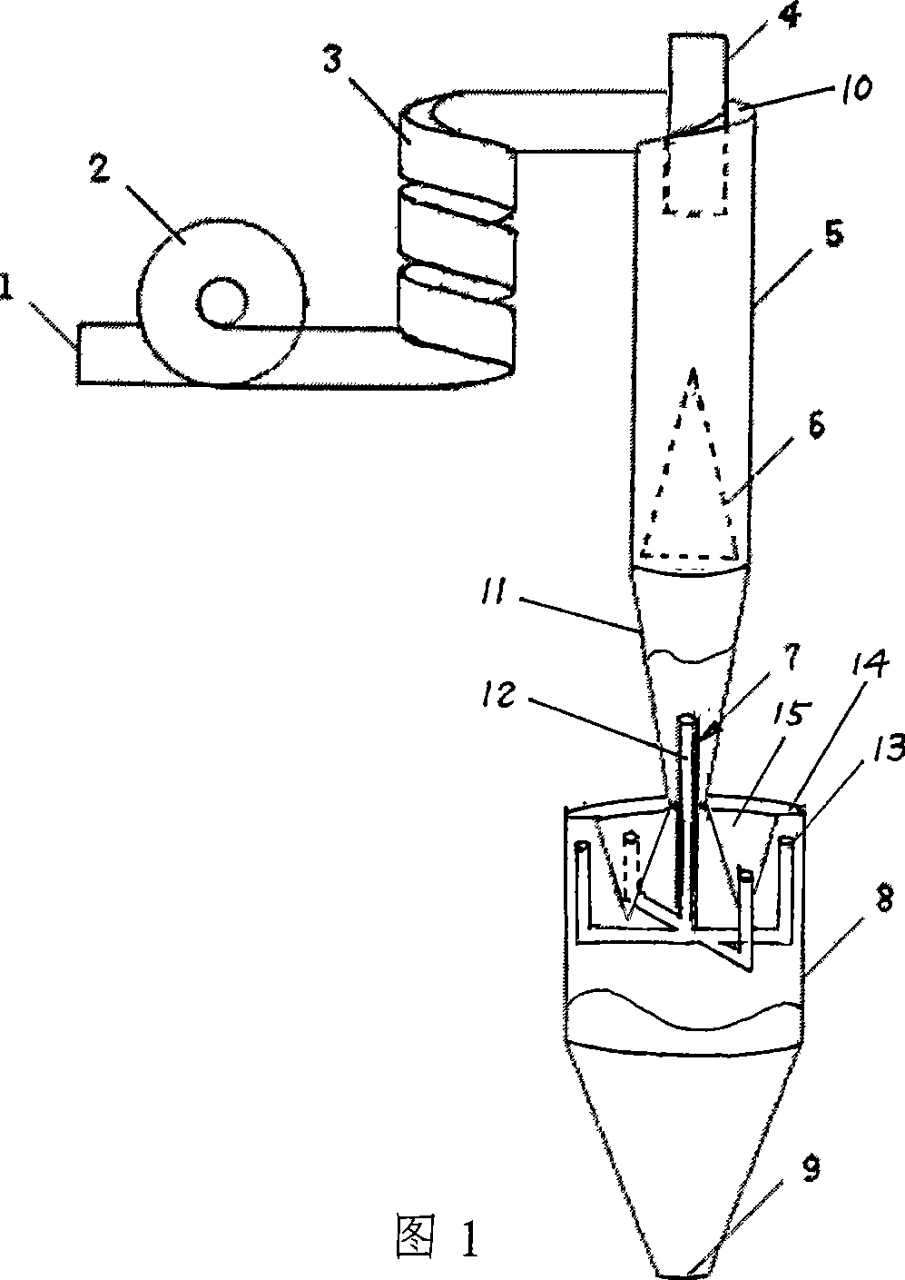
[0016] Example 1. A multi-effect cyclone separator, such as figure 1 , figure 2 Shown. It includes the main body shell. The main body shell includes an upper cylindrical body 5, a spiral top cover plate 10 fixed on the upper cylindrical body 5, and a lower inverted cone cylindrical body 11 fixed on the lower end of the upper cylindrical body 5. The exhaust pipe 4 is installed in the middle of the spiral top cover plate 10 and extends into the upper cylindrical body 5. An ash bin 8 with an ash discharge port 9 at the lower end is fixed at the lower end of the inverted cone shell 11. The air inlet 1 is tangentially installed on the upper end of the upper cylindrical body 5 via the vertical α-shaped first-stage pre-separation spiral pipe 2 and the second-stage pre-separation spiral pipe 3 connected in sequence. The cross sections of the air inlet 1 and the first-stage pre-separation spiral pipe 2 and the second-stage pre-separation spiral pipe 3 are all rectangular. The rotat...


PUM


Abstract

Disclosed is a multi-effect cyclone separator. A shell of a main body of the separator comprises an upper cylinder, a spiral top cover plate and a lower reverse conical cylinder. An air exhaust pipe extends into the cylinder. An ash bin is fixed at the lower end of the reverse conical shell. An air inlet is tangentially arranged at the upper end of the cylinder through a vertical Alpha-shaped first grade pre-separating spiral tube and a second grade pre-separating spiral tube sequentially connected with each other. The cross sections of the air inlet as well as the first grade pre-separating spiral tube and the second grade pre-separating spiral tube are all rectangles. The rotation angles of the first grade pre-separating spiral tube and the second grade pre-separating spiral tube are 360 degrees and 1080 degrees respectively. A throttling steady flow wimble cone is fixed at the lower part of the cylinder. A gas suction pipe is disposed at the upper part of the ash bin, and a V-shaped ring groove is arranged in the middle of a top cover plate of the ash bin. The cyclone separator has advantages of small pressure drop, high separation efficiency to submicron particles and small scaling effect. The dust concentration during air exhaust meets the environmental protection requirements. The cyclone separator effectively eliminates the secondary flow in a flow field, and has advantages of stable flow pattern, low gas velocity, low equipment abrasion and long service life. The cyclone separator can replace cloth bags and electrostatic dust collectors to undertake the tail end dust removal of dust-laden gas.

Description

Technical field [0001] The invention belongs to the technical field of cyclone separators, and more specifically relates to the innovative design of multi-effect cyclones. Background technique [0002] Traditional various types of ordinary and high-efficiency cyclones generally have problems such as short-circuit flow at the exhaust port and entrainment of the lower ash ring, and the amplification effect is significant. As the size of the separator increases, the pressure drop increases sharply, and the separation efficiency decreases significantly. The separation efficiency for particles below 3μm is very low, and even the particles within the range of 3-10μm cannot guarantee 100% removal. Under strict environmental protection requirements, it cannot meet the requirements of terminal dust removal. [0003] In addition, there are various secondary flows in the flow field in the existing cyclone separators, the flow pattern is not stable enough, the equipment wears a lot, and the ...

Claims


Application Information

Patent Timeline
Patent Type & Authority Patents(China)
IPC IPC(8): B04C5/02B04C5/04B04C5/181B04C5/12
Inventor 王立新李会平
Owner QINGDAO UNIV OF SCI & TECH
Learn More