Continuous operation type active charcoal producing apparatus and process

a technology of active charcoal and continuous operation, which is applied in the direction of lighting and heating apparatus, physical/chemical process catalysts, furnaces, etc., can solve the problems of high cost, high cost, and inability to meet the needs of production, so as to improve commercial production, shorten the life of the apparatus, and achieve high activation. degree

Inactive Publication Date: 2010-08-10
KUREHA KAGAKU KOGYO KK
View PDF4 Cites 5 Cited by
  • Summary
  • Abstract
  • Description
  • Claims
  • Application Information

AI Technical Summary

Benefits of technology

[0006]Accordingly, a principal object of the present invention is to provide an apparatus and a process by which even activated carbon at a high degree of activation can be continuously produced at a high yield.
[0012]Then, the present inventors have acquired a concept that it is effective in order to solve the above-mentioned problem to increase the aperture rate of an upper horizontal perforated partitioning plate compared with a lower horizontal perforated partitioning plate, thereby effecting a relative decrease in fluidizing gas velocity through the perforations, in view of the above-mentioned lowering in terminal velocity of carbon particles and increase in fluidizing gas volume along with the progress of activation reaction, and have confirmed the effect thereof through experiments (as shown in Examples described hereinafter) to arrive at the present invention.

Problems solved by technology

This requires the raising and lowering of the apparatus temperature for each batch, thus resulting in much loss of time and energy.
Further, the temperature change causes heat stress distortion, thus being liable to cause problems such as deterioration of furnace structure and materials.
However, in order to obtain a uniform conversion as obtained by a batchwise operation, a large number of stages as many as several tens of stages, is required and is not realistic.
However, if this process is applied to production of a high-performance activated carbon having a high degree of activation, it has been found that the activated carbon cannot be obtained at a desired yield (as shown in Comparative Example 2 appearing hereinafter).

Method used


Image

  • Continuous operation type active charcoal producing apparatus and process
  • Continuous operation type active charcoal producing apparatus and process
  • Continuous operation type active charcoal producing apparatus and process

Examples


example 1

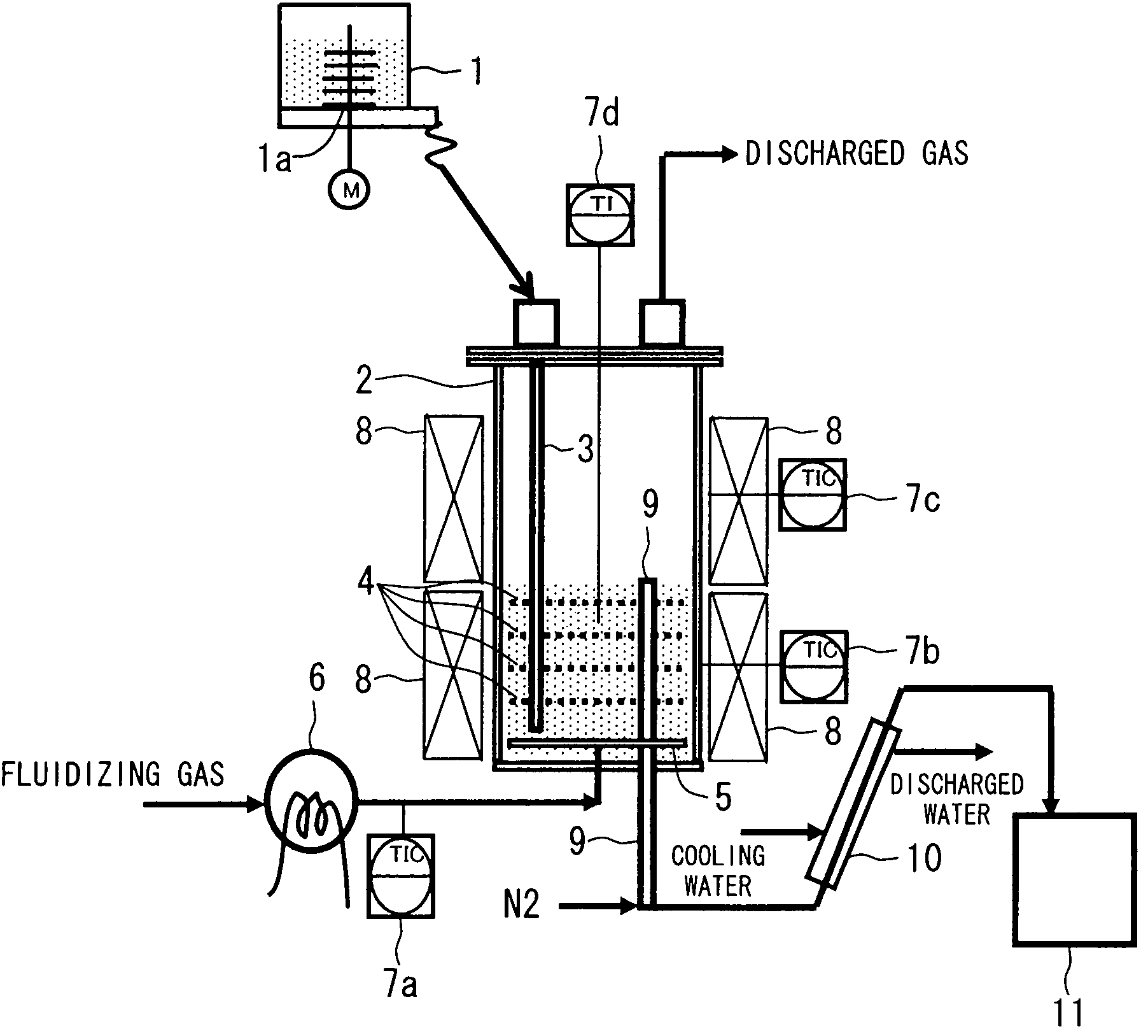
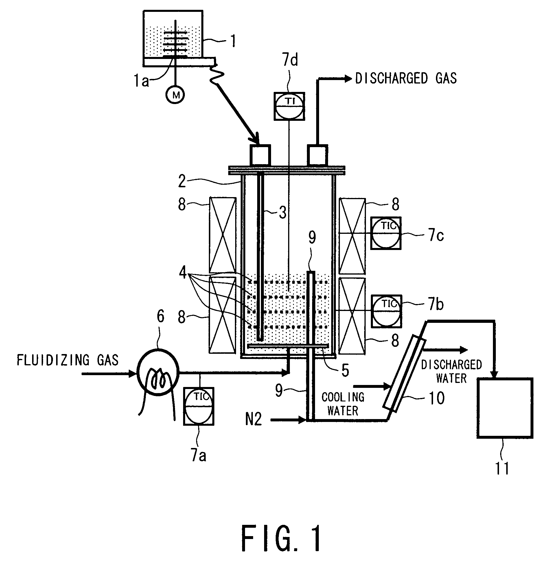
[0055]In an apparatus for continuous production of activated carbon as schematically illustrated in FIG. 1, an activated carbon production apparatus main body 2 was disposed to have an inner diameter of 300 mm and provided with an activated carbon discharge tube 9 having an upper end opening at a height of 460 mm from the apparatus bottom plate and four horizontal perforated partitioning plates 4 with a spacing in a height direction of 100 mm each, wherein the respective partitioning plates disposed from the uppermost to the lower positions were provided with perforations of 12.0 mm, 10.9 mm, 9.8 mm and 8.5 mm, respectively, in diameter, in a square arrangement at a pitch of 25 mm in each case to provide aperture rates of 18%, 15%, 12%, and 9%, respectively. In the activated carbon apparatus main body 2, the internal temperature detected by a thermometer 7d was adjusted at 820° C. by a side wall heater 8, and a mixture fluidizing gas comprising nitrogen 10 vol. % and steam 90 vol. %...

example 2

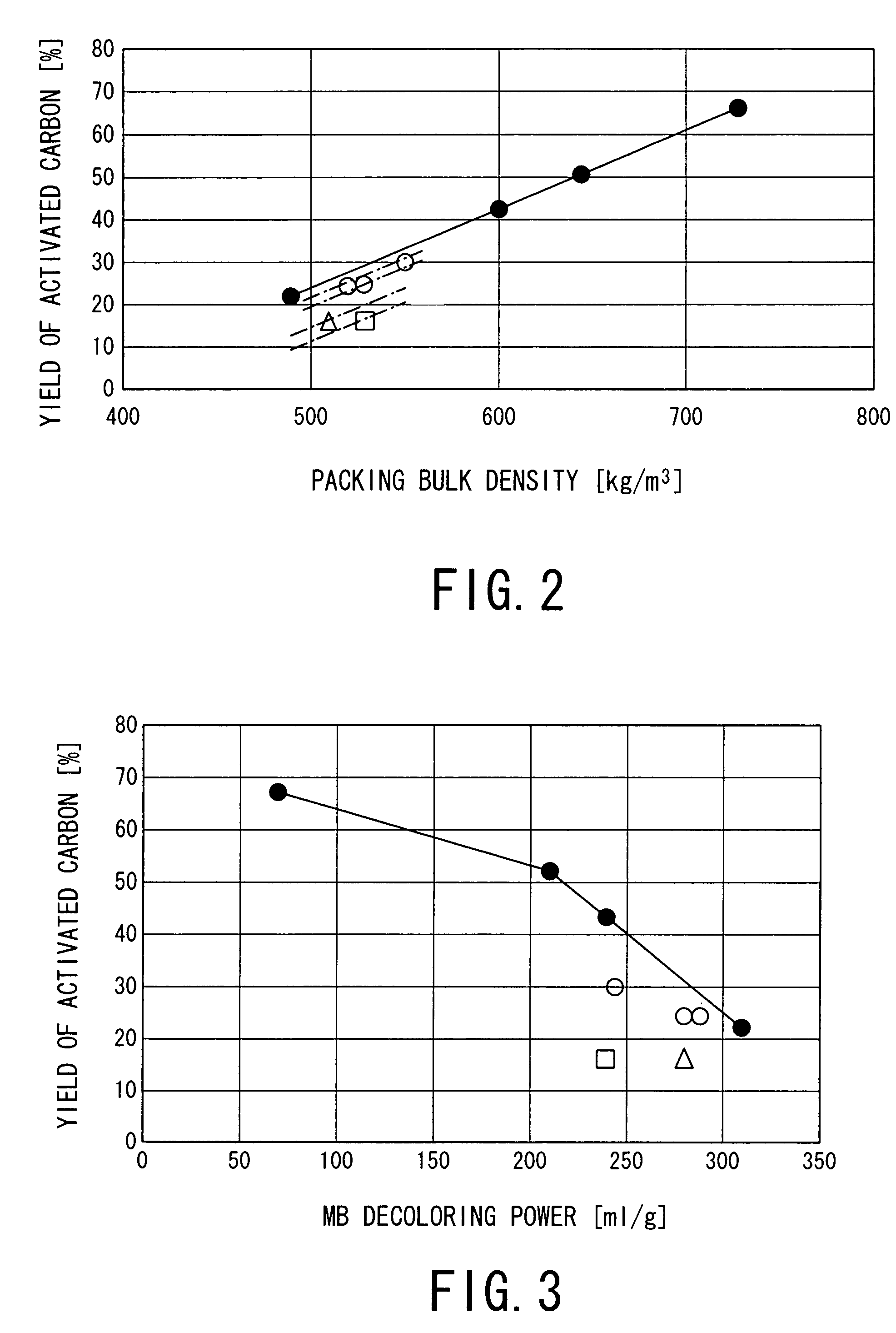
[0056]An identical apparatus as used in Example 1 was used except that among the four horizontal perforated partitioning plates*, only the two plates having aperture rates of 18% and 15%, respectively, were left and the lower two horizontal perforated partitioning plates were removed. When the operation of Example 1 under identical compositions and flow rates of feed carbon and fluidizing gas and an identical operation temperature was performed, an activated carbon having a packing bulk density of 530 kg / m3 was obtained in the activated carbon recovery vessel 11 at a yield of 24 wt. % with respect to the feed carbon and showed a Methylene Blue decoloring power of 280 ml / g.

example 3

[0057]An identical apparatus as used in Example 1 was used except that among the four horizontal perforated partitioning plates, the uppermost and lowermost horizontal perforated partitioning plates having aperture rates of 18% and 19%, respectively, were removed, and the middle two horizontal perforated partitioning plates having aperture rates of 15% and 12% were moved to the positions of the uppermost and second horizontal perforated partitioning plates. When the operation of Example 1 was performed under identical composition and flow rate of fluidizing gas and an identical operation temperature except for changing the feed rate of an identical composition of the feed carbon from 1000 g / h to 2000 g / h, an activated carbon having a packing bulk density of 550 kg / m3 was obtained in the activated carbon recovery vessel 11 at a yield of 30 wt. % with respect to the feed carbon and showed a Methylene Blue decoloring power of 240 ml / g.


PUM

PropertyMeasurementUnit
temperatureaaaaaaaaaa
particle packing bulk densityaaaaaaaaaa
particle sizeaaaaaaaaaa

Abstract

A vertical multi-stage fluidized bed apparatus including a plurality of horizontal perforated partitioning plates disposed therein so as to partition the apparatus is provided, wherein an upper horizontal perforated partitioning plate is set to have a larger aperture rate than a lower horizontal perforated partitioning plate. From a lower part of the apparatus, feed carbon and fluidizing gas are continuously supplied so as to provide a gas superficial velocity in the fluidized bed which is 2-4 times a minimum fluidizing velocity of the feed carbon, thereby subjecting the feed carbon to fluidization with the fluidizing gas and activation with steam at 750-950° C. simultaneously to discharge activated carbon continuously from an upper part of the apparatus. As a result, activated carbon of even a high degree of activation is produced at a high yield comparable to that obtained in a batchwise operation.

Description

TECHNICAL FIELD[0001]The present invention relates to an improvement in apparatus and process for continuous production of activated carbon according to the steam activation process using a vertical multi-stage fluidized bed apparatus partitioned by a plurality of horizontal perforated partitioning plates.BACKGROUND ART[0002]Steam activation reaction for production of activated carbon or active charcoal is ordinarily performed by causing steam to react on starting or feed carbon at a high temperature of 750-950° C. to result in fine pores in the feed carbon through water gas reaction, thereby producing activated carbon. As the apparatus for producing activated carbon, a rotary kiln, a moving bed, a fluidized bed, etc., have been conventionally used. Among these, a fluidized bed is characterized by a fast heat-exchange speed to provide a uniform particle temperature as a whole. Accordingly, a batchwise operation thereof affords a uniform reaction in the entire apparatus and can obvia...

Claims


Application Information

Patent Timeline
Patent Type & Authority Patents(United States)
IPC IPC(8): B01J8/18C01B31/08F27B15/08C01B32/336
CPCC01B31/088C01B31/10C01B32/39C01B32/336
Inventor OHASHI, HIROAKIYAMANOBE, YASUYOSHI
Owner KUREHA KAGAKU KOGYO KK
Why Eureka
Try Eureka