Flue gas desulfurizing tower and flue gas desulfurization and wastewater treatment method

A desulfurization tower and flue gas technology, which is applied in the direction of gaseous effluent wastewater treatment, chemical instruments and methods, water/sewage multi-stage treatment, etc. It can solve the problem of many equipment, large floor area, and inability to upgrade and transform equipment and boiler space, etc. question

Active Publication Date: 2018-10-09
CHINA PETROLEUM & CHEM CORP +1
View PDF8 Cites 5 Cited by
  • Summary
  • Abstract
  • Description
  • Claims
  • Application Information

AI Technical Summary

Problems solved by technology

The above-mentioned wet desulfurization technology includes flue gas desulfurization, desulfurization wastewater oxidation treatment or regeneration unit. The process is long, there are many equipments, and the floor area is large, which seriously restricts the construction and upgrading of dust removal and desulfurization devices. Some devices and boilers are due to lack of There is not enough space to upgrade and renovate, resulting in smoke emission indicators that cannot meet the current national standards and forced to stop work or demolish and rebuild

Method used


Image

  • Flue gas desulfurizing tower and flue gas desulfurization and wastewater treatment method
  • Flue gas desulfurizing tower and flue gas desulfurization and wastewater treatment method
  • Flue gas desulfurizing tower and flue gas desulfurization and wastewater treatment method

Examples


Embodiment

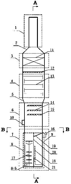
[0082] A flue gas dedusting and desulfurization tower, from top to bottom are the flue gas discharge area 1, the mist removal area 3, the tower area 4, the spray area 6 and the waste water treatment area 7, the flue gas discharge area 1 and the mist removal area 3 It is connected by a cone-shaped diameter 2, and below the demisting area 3 is a tray area 4, and the tray area 4 and the spray area 6 are connected by an inverted cone-shaped diameter 5, and below the spray area 6 is a waste water treatment area 7.

[0083] A wet electrostatic demister 11 is arranged in the demisting area 3, a liquid distributor 12 is arranged under the wet electrostatic demister 11, a tray area 4 is arranged under the liquid distributor 12, and a total of 4 layers of trays are arranged in the tray area 4. A sieve tray is selected; the spray area 6 is provided with three layers of spray pipelines 14, the distance between the spray pipelines 14 is 2m, and the atomizing nozzles 15 are evenly arranged o...


PUM

PropertyMeasurementUnit
heightaaaaaaaaaa

Abstract

The invention discloses a flue gas desulfurizing tower and a flue gas desulfurization and wastewater treatment method. The flue gas desulfurizing tower sequentially comprises a flue gas exhaust area,a demist area, a tower tray area, a spraying area and a wastewater treatment area from top to bottom; the flue gas exhaust area and the demist area are connected through a cone deformation diameter, the tower tray area and the spraying area are connected through an inverted cone deformation diameter; the wastewater treatment area is divided by a vertical partition plat I from the center into an oxidation flocculation area and a circulation clear liquid area, the circulation clear liquid area is completely separated from the oxidation flocculation area and the spraying area through a partitionplate II from the top part of the circulation clear liquid area; the oxidation flocculation area is provided with a stirring device; and the vertical partition plate I is provided with a filter medium. The flue gas is subjected to dust removal, desulfurization and wastewater treatment in one tower, the flue gas is used to stir the wastewater to implement the operations of oxidation flocculation and concentration, the difference of the liquid levels of the two sides of the vertical partition plate is used as a driving force to filter the desulfurization wastewater, the occupied area is greatlyreduced, and the costs for the construction and transformation of the device and the operation cost of the device are obviously lowered.

Description

technical field [0001] The invention belongs to the field of industrial waste gas purification, and relates to a flue gas desulfurization tower and a flue gas desulfurization and wastewater treatment method. Background technique [0002] Sulfur dioxide and dust are contained in boiler flue gas and flue gas emitted by factories. Sulfur dioxide and dust are the main components of air pollutants. one. [0003] Wet desulfurization has the advantages of high desulfurization rate, reliable device operation, and simple operation. Therefore, the existing flue gas desulfurization technologies in various countries in the world are mainly based on wet desulfurization. Traditional wet desulfurization technologies mainly include limestone-gypsum desulfurization, double alkali desulfurization, sodium alkali desulfurization, ammonia desulfurization and so on. The above-mentioned flue gas desulfurization technology mainly adopts countercurrent spraying. The alkaline slurry is sprayed from...

Claims


Application Information

Patent Timeline
Patent Type & Authority Applications(China)
IPC IPC(8): B01D53/50B01D53/78B01D53/75B01D47/12C02F9/04C02F103/18
Inventor 李磊王海波刘忠生李欣韩天竹杨秀娜
Owner CHINA PETROLEUM & CHEM CORP
Why Eureka
Try Eureka