Load-transfer machine for tyres

A loader and tire technology, applied to conveyor objects, lifting devices, lifting frames, etc., can solve the problems of relatively high workpiece positioning requirements, large floor space, and small transfer volume, etc., to ensure production tact and floor space The effect of small size and large reprint volume

Inactive Publication Date: 2009-03-25
MIRACLE AUTOMATION ENG CO LTD
View PDF0 Cites 6 Cited by
  • Summary
  • Abstract
  • Description
  • Claims
  • Application Information

AI Technical Summary

Problems solved by technology

[0002] The existing tire reloading machine is to realize the reloading of the workpiece by means of a rolling bed, which occupies a large area and has a small reloading capacity, and the cost is high; moreover, the positioning of the workpiece is relatively high when reloading

Method used


Image

  • Load-transfer machine for tyres
  • Load-transfer machine for tyres
  • Load-transfer machine for tyres

Examples


Embodiment Construction

[0011] The present invention will be further described below in conjunction with specific drawings and embodiments.

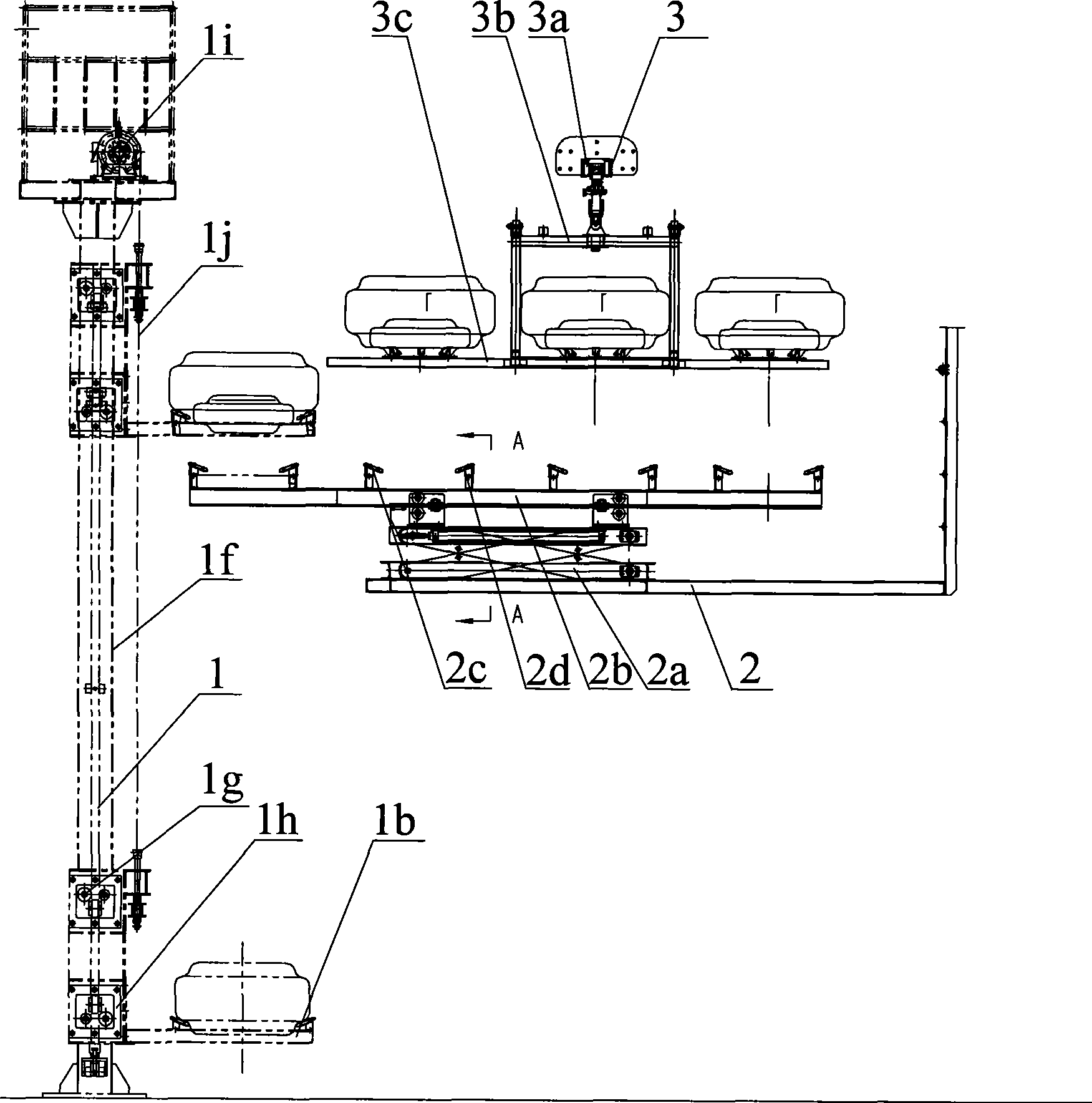
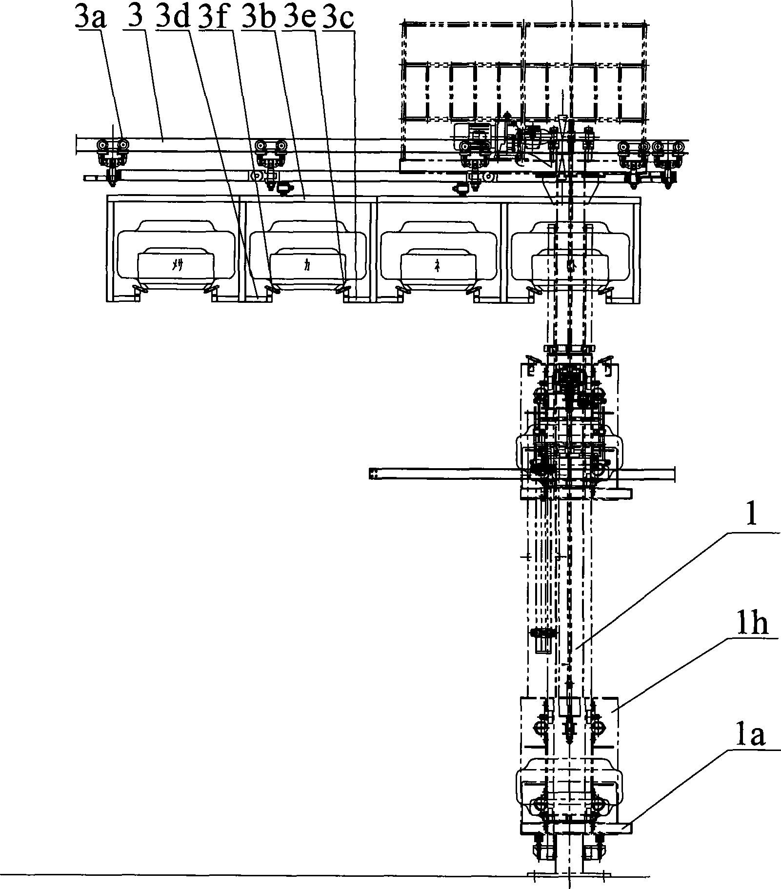
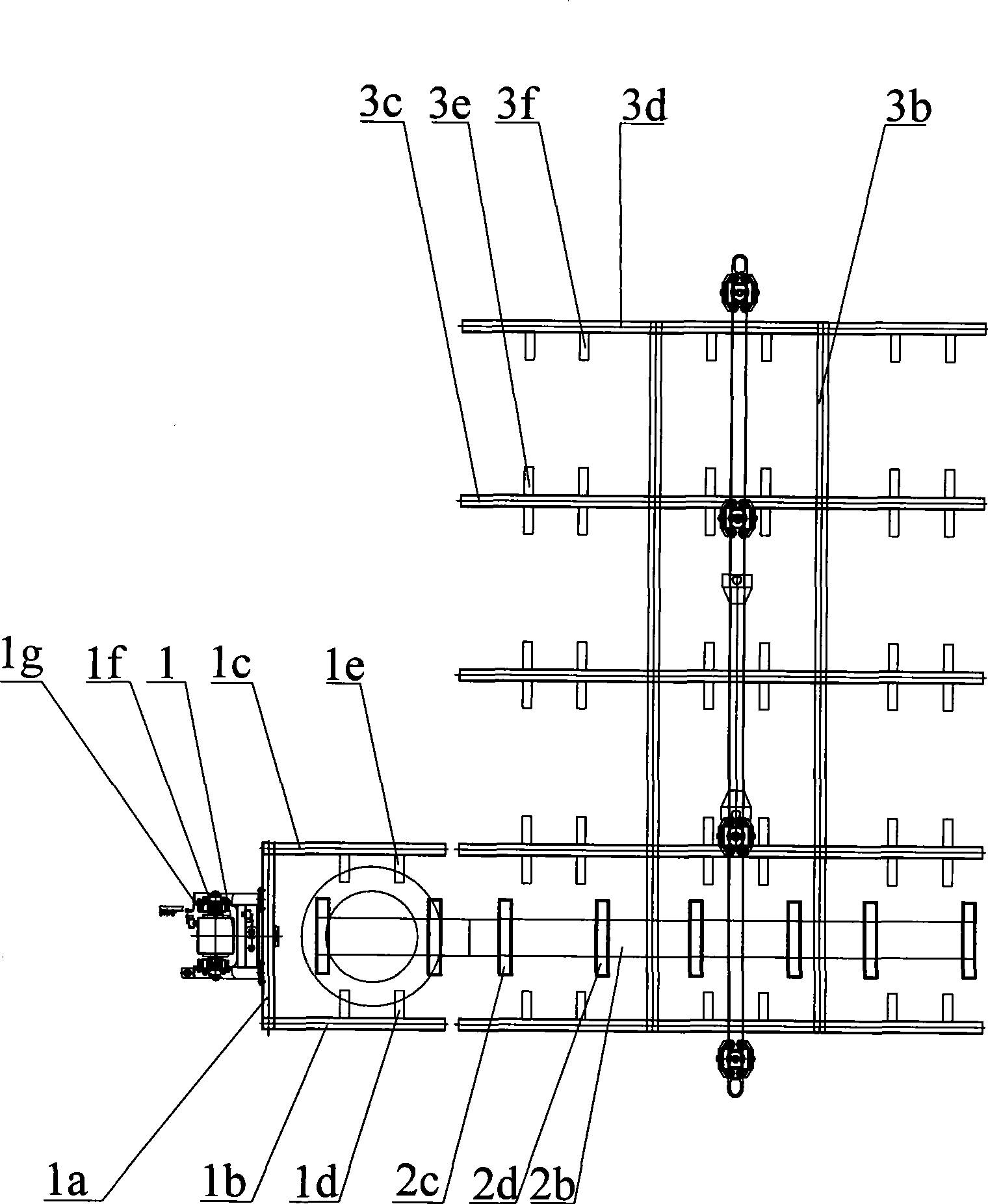
[0012] As shown in the figure: the tire transfer machine of the present invention is mainly composed of a column 1, a lifting carriage 1a, a first load bar 1b, a second load bar 1c, a first bracket 1d, a second bracket 1e, a lift rail 1f, a lift Traveling wheel 1g, sliding sleeve 1h, driving sprocket 1i, driving chain 1j, reloading base body 2, lifting platform device 2a, telescopic reloading rod 2b, first reloading bracket 2c, second reloading bracket 2d, conveying track 3, The traveling wheels 3a, the conveying frame body 3b, the third bearing rod 3c, the fourth bearing rod 3d, the third bracket 3e, and the fourth bracket 3f are composed of.

[0013] It includes the lifting carriage 1a and its lifting drive device arranged on the column 1, the first bearing rod 1b and the second bearing rod 1c protruding laterally are arranged at intervals on the inner and ou...


PUM


Abstract

The invention relates to a tire transferring conveyor used for transferring tires of different lines. An elevation sliding frame is arranged on a column and a first bearing rod and a second bearing rod are arranged on the elevation sliding frame. A first bracket extending to the second bearing rod is arranged on the side wall of the first bearing rod and a second bracket extending to the first bearing rod is arranged on the side wall of the second bearing rod. A first transferring bracket and a second transferring bracket are arranged on the top end of a flexible transferring rod and the distance between the inner end and the outer end of the first and second transferring brackets is less than the clearance between the ends of the first and second brackets; a conveying frame is provided with a third bearing rod and a fourth bearing rod; a third bracket extending to the fourth bearing rod is arranged on the side wall of the third bearing rod and a fourth bracket extending to the third bearing rod is arranged on the side wall of the fourth bearing rod; the distance between the inner end and the outer end of the first and second transferring brackets is less than the clearance between the corresponding ends of third and fourth brackets. The tire transferring conveyor has the simple structure, small occupied space and high transferring capacity, and can ensure the manufacturing efficiency, low noise and convenient maintenance.

Description

technical field [0001] The invention relates to a tire transfer machine used for transferring tires between different line bodies, belonging to the field of conveying machinery automation. Background technique [0002] The existing tire reloading machine realizes the reloading of the workpiece by means of a rolling bed, which occupies a large area and has a small reloading capacity, and the cost is relatively high; moreover, the positioning of the workpiece is relatively high when reloading. Contents of the invention [0003] The purpose of the present invention is to overcome the deficiencies in the prior art and provide a tire transfer machine with simple structure, small footprint, large transfer capacity, low noise and convenient maintenance. [0004] According to the technical solution provided by the present invention, the tire transfer machine includes a lifting carriage and its lifting drive device arranged on the column, and the first load bar and the second horiz...

Claims


Application Information

Patent Timeline
Patent Type & Authority Applications(China)
IPC IPC(8): B65G47/52B65G47/82B66F7/00
Inventor 吴来水汪海艳
Owner MIRACLE AUTOMATION ENG CO LTD
Why Eureka
Try Eureka