Hemming production line of face cloth

A production line and hem technology, which is applied to the thread cutting mechanism, sewing equipment, sewing machine components and other directions in the sewing machine, can solve the problems of difficulty in guaranteeing production quality and low production efficiency, and achieves improved production efficiency, simple structure and high degree of automation. Effect

Active Publication Date: 2009-03-25
张广生
View PDF0 Cites 28 Cited by
  • Summary
  • Abstract
  • Description
  • Claims
  • Application Information

AI Technical Summary

Problems solved by technology

[0003] The purpose of the present invention is to solve the problems that the production of the existing square scarves is all done by hand, the production efficiency is low, and the production quality is difficult to guarantee, and a kind of square scarf hemming production line is provided.

Method used


Image

  • Hemming production line of face cloth
  • Hemming production line of face cloth
  • Hemming production line of face cloth

Examples


specific Embodiment approach 1

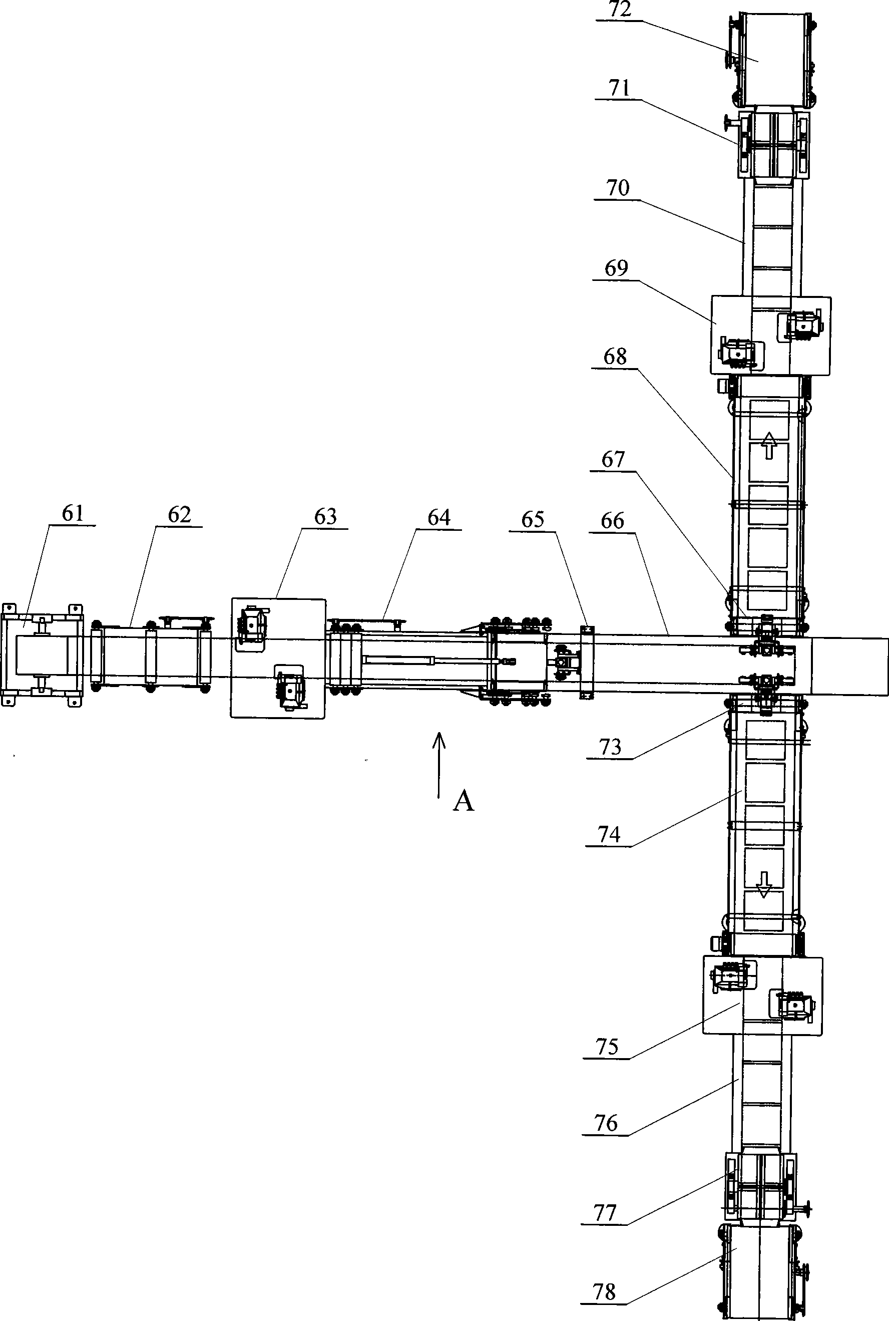
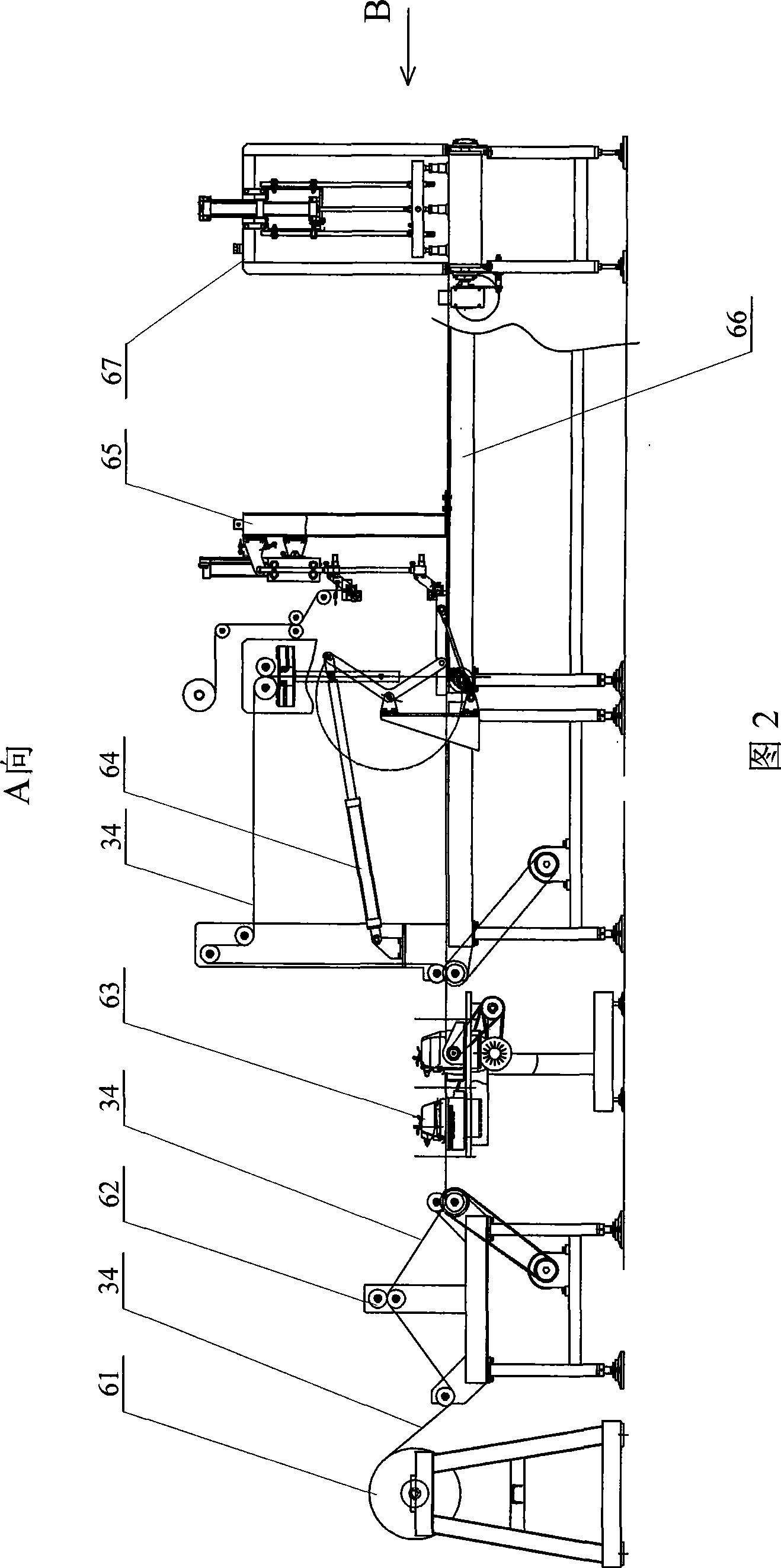
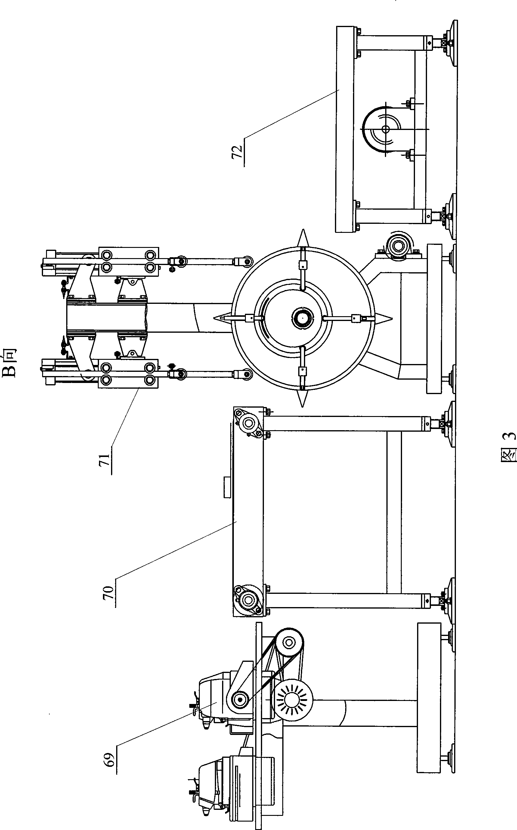
[0006] Specific implementation mode one: (see figure 1 ~ Figure 3) This embodiment includes a damping core setting machine 61, a synchronous conveyor 62, a first double head overlock sewing machine 63, a reclaiming conveyor 64, a first conveyor 66, a first horizontal reclaimer 67, a first Second conveyor 68, second double-head overlock sewing machine 69, third conveyor 70, first head cutting device 71, second horizontal reclaimer 73, fourth conveyor 74, third double-head overlock sewing machine 75. The fifth conveyor 76 and the second head cutting device 77, the damping core setting machine 61, the synchronous conveyor 62, the first double-head overlock sewing machine 63, the reclaiming conveyor 64 and the first conveyor 66 are arranged in sequence, The first transverse reclaimer 67 and the second transverse reclaimer 73 are respectively arranged on the both sides of the first conveyor 66 rear portion, and the back of the first transverse reclaimer 67 is provided with the seco...

specific Embodiment approach 2

[0007] Specific implementation mode two: (referring to Fig. 21~ Figure 23 ) In this embodiment, a labeling machine 65 is added, and the labeling machine 65 is arranged on the top of the first conveyor 66. Adsorber 104, rotary cylinder 105, second negative pressure adsorber 107, slide bar 109, support arm 110, rotating shaft 111, upper label support roller 112, lower label support roller 113, label drive roller 114, belt roller The support 116 and the total support 117 are formed, the lifting cylinder 102 is fixed on the top of the total support 117 side, the support 116 with rollers is fixed on the general support 117 on the lower side of the lifting cylinder 102, the slide bar 109 and the support with the rollers 116 is slidingly connected, and one side of support arm 110 is fixedly connected with the lower end of slide bar 109, and the free end of the cylinder rod 108 of lifting cylinder 102 is fixedly connected with support arm 110, and the other side of support arm 110 is...

specific Embodiment approach 3

[0009] Specific implementation mode three: (see Figure 17 ) The synchronous conveyor 62 of the present embodiment is made up of synchronous frame 35, active guide roller 46, intermediate guide roller 47, passive guide roller 48, motor 49 of synchronous conveyor and synchronous conveyor belt 50, and intermediate guide roller 47 is arranged on In the middle position above the synchronous frame 35, the passive guide roller 48 is arranged on the synchronous frame 35 and near one end of the damping unwinder 61, and the active guide roller 46 is arranged on the synchronous frame 35 and near the first double head overlock One end of the machine 63, between the driving guide roller 46 and the motor 49 of the synchronous conveyor, is connected by a synchronous conveyor belt 50 transmission.


PUM


Abstract

The invention provides a kerchief hemming-stitch production line, and relates to a kerchief production line. The invention aims at solving the problems that the existing kerchief is produced by hand, the production efficiency is low and the production quality is difficult to be guaranteed. The invention includes a damping core arranging machine, a synchronous conveyer, a first double head overlock machine, a reclaiming conveyer and a first conveyer which are sequentially arranged; a first transverse reclaiming machine and a second transverse reclaiming machine are respectively arranged at both sides of the rear part of the first conveyer, and a second conveyer, a second double head ovelock machine, a third conveyer and a first end-cutting device are sequentially arranged behind the first transversal reclaiming machine; a fourth conveyer, a third double head overlock machine, a fifth conveyer and a second end-cutting device are sequentially arranged behind the second transversal reclaiming machine. The invention adopts the first double head overlock machine to overlock the two sides of the cloth and adopts the second or third double head overlock machine to overlock the other two sides of the kerchief, which can improve the production efficiency by 5-6 times compared with the manual operation.

Description

technical field [0001] The invention relates to a square towel production line. Background technique [0002] At present, the production of the existing square scarf is still in the process of manual production. Its production process is: the round roll blank is cut into circles, the cut blank is unfolded and stacked flat, and then cut into pieces according to the size of the square scarf; Overlocking and pasting trademarks on the periphery of the square scarves cut into blocks is all done by hand in this production process. Its productivity is low and the production quality is difficult to guarantee. Contents of the invention [0003] The purpose of the present invention is to provide a scarf hemming production line to solve the problems that the production of the existing square scarves is all done by hand, the production efficiency is low, and the production quality is difficult to guarantee. The present invention includes a damping core setting machine, a synchronous ...

Claims


Application Information

Patent Timeline
Patent Type & Authority Applications(China)
IPC IPC(8): D05B1/20D05B37/00D05B27/00D05B65/00B65C9/20
Inventor 张广生徐志英
Owner 张广生
Why Eureka
Try Eureka