Traffic sign line labeling method and system thereof

A technology of traffic signs and traffic markings, applied in the marking method and system field of traffic signs and markings, to achieve the effect of high reliability, low cost and clear images

Inactive Publication Date: 2009-03-25
高玉宗
View PDF0 Cites 27 Cited by
  • Summary
  • Abstract
  • Description
  • Claims
  • Application Information

AI Technical Summary

Problems solved by technology

In this way, the traffic jam section can borrow the idle lane on the opposite side, which reduces the pressure on the traffic jam section, and solves the problem of traffic jam in the direction of going to the city during working hours and fewer vehicles in the direction of going out of the city, and traffic jam in the direction of going out of the city and fewer vehicles in the direction of going to the city during off-duty hours.

Method used


Image

  • Traffic sign line labeling method and system thereof
  • Traffic sign line labeling method and system thereof
  • Traffic sign line labeling method and system thereof

Examples


Embodiment 1

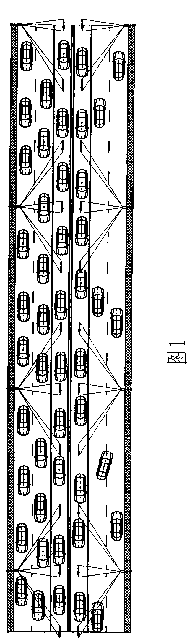
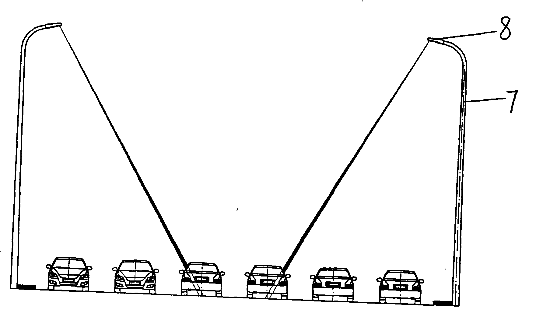
[0042] Figure 4 It is a road schematic diagram of a certain crossroad of the present invention, and Fig. 1 is a schematic diagram of road traffic conditions after the indicating arrow has been changed in Embodiment 1 of the present invention, image 3 It is a schematic diagram of a laser generator installed on a street light pole projecting laser light onto the road.

[0043] like Figure 4 As shown, road marking paint is used to draw lane dividing lines on the road surface, and there is no intermediate barrier between the two directions. like image 3As shown, with the laser generator 8 that is installed on the street lamp 7 light poles, irradiate the road surface indicating arrow, and the laser generator 8 selects the laser with low power to avoid affecting the driver's line of sight to form light pollution. The laser generator 8 includes a laser generator module and a control module connected to the laser generator module. The laser generator module emits laser light thro...

Embodiment 2

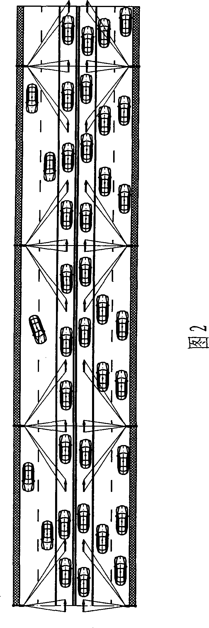
[0048] Figure 4 It is a road schematic diagram of a certain crossroad of the present invention, and Fig. 2 is a schematic diagram of road traffic conditions after the indicating arrow has been changed in the present embodiment, image 3 It is a schematic diagram of a laser generator installed on a street light pole projecting laser light onto the road.

[0049] like Figure 4 As shown, road marking paint is used to draw lane dividing lines on the road surface, and there is no intermediate barrier between the two directions. like image 3 As shown, the road surface indicator arrow is irradiated with the laser generator 8 installed on the light pole of the street lamp 7 (it can also be directly installed at the position of the isolation belt on the ground, and the three-dimensional pattern formed by upward emission is connected to form the isolation belt). 8 Choose a laser with low power to avoid affecting the driver's sight and form light pollution. The laser generator 8 inc...

Embodiment 3

[0053] Figure 4 It is a road schematic diagram of a certain intersection of the present invention.

[0054] like Figure 4 As shown, in embodiment 1, when the direction of the indicator arrow of lane 4 is changed from the direction of going out of the city (i.e. upward) to the direction of entering the city (i.e. downward), the laser beam sent by laser generator 8 forms a merge sign above lane 4 ,like Figure 5 , so that the cars on lane 4 can merge into lane 5 immediately; a traffic diversion sign is placed above lane 3, such as Image 6 , so that the cars in lane 3 can be diverted to lane 4 to alleviate traffic jams.

[0055] like Figure 4 As shown, in embodiment 2, when the direction of the indicator arrow of lane 3 is changed from the direction of entering the city (i.e. downward) to the direction of leaving the city (i.e. upward), the laser generator 8 is used to form a merge sign above the lane 3 ,like Figure 5 , so that the cars on lane 3 can merge into lane 2 ...


PUM


Abstract

The invention relates to a method and a system for making a traffic sign marking. The traffic sign marking comprises a traffic sign and a traffic marking, and also traffic facilities; a laser generator is used for generating laser to form three-dimensional or two-dimensional traffic sign marking, and the laser beam generated by the laser generator can be adjusted to change the traffic sign marking. By adopting the method and the system, the vacant lane in the opposite direction can be utilized to relieve the pressure of traffic jam sections and solve the problem that traffic jam appears in the downtown direction and less cars go in the uptown direction when people go to work, and the traffic jam appears in the uptown direction and less cars go in the downtown direction when people get off work.

Description

technical field [0001] The invention relates to the field of traffic signals, in particular to a marking method and system for marking lines of traffic signs. Background technique [0002] With the continuous progress of the society and the rapid development of the economy, the role of transportation in the development of the national economy has become more and more prominent. In recent years, the number of cars in the world has increased significantly. The demand for road traffic is growing rapidly, the contradiction between people, vehicles, and roads is becoming increasingly prominent, and the situation of traffic congestion and road traffic safety is severe. In order to maintain road traffic order, ensure road traffic safety, and provide strong legal protection for economic and social development, various traffic laws and regulations stipulate that vehicles and pedestrians on the road should be scientifically assigned the right of way, so that they can pass in an orderl...

Claims


Application Information

Patent Timeline
Patent Type & Authority Applications(China)
IPC IPC(8): G08G1/09E01F9/08
CPCG08G1/096783
Inventor 高玉宗
Owner 高玉宗
Why Eureka
Try Eureka