
Conductive rubber member

A conductive and rubber technology, which is applied in the direction of electrography, electric recording process using charge pattern, equipment of electric recording process applying charge pattern, etc. requirements, etc., to achieve the effect of small resistance value changes

Active Publication Date: 2009-04-01
SYNZTEC
View PDF5 Cites 5 Cited by
  • Summary
  • Abstract
  • Description
  • Claims
  • Application Information

AI Technical Summary

Problems solved by technology

However, in this case, for example, using a surface treatment liquid that is relatively difficult to impregnate the conductive elastic layer to form a relatively thin surface treatment layer may not be able to obtain a sufficient effect as a surface treatment layer, and in some cases it may not be sufficient. Respond to usage requirements

Method used


Image

  • Conductive rubber member
  • Conductive rubber member
  • Conductive rubber member

Examples


Embodiment 1

[0062]

[0063] To 100 parts by weight of trifunctional polyether-based polyol MN-3050 (manufactured by Mitsui Takeda Homikar), 3 parts by weight of Hitchen Black EC (manufactured by Hitchen Black Inta-Nase Yonal Co.) and Asahi #60 (made by Asahi Ka-bon) were added. ) in 5 parts by weight to disperse to a particle size below 20 μm, and after temperature adjustment to 80° C., defoaming and dehydration operations were carried out for 6 hours under reduced pressure to obtain liquid A. On the other hand, 10 parts by weight of Coronet C-HX (manufactured by Nippon Polyuretan Co., Ltd.) was added and mixed to 22 parts by weight of Premium Polyma-Ajiplen L100 (manufactured by Uniroyal Co., Ltd.), and the temperature was adjusted to 80° C. to obtain liquid B. Mix liquid A and liquid B and inject it into an iron pipe mold with a diameter of 23mm that is preheated to 120°C with a shaft (φ8mm, 1:270mm) in the center, and heat at 120°C for 120 minutes to obtain A roller having a conducti...

Embodiment 2

[0069]

[0070] 0.5 parts by weight of tetraethylammonium perchlorate (manufactured by Kanto Chemical Co., Ltd.) as a conductive agent was kneaded with a roll mixer with respect to 100 parts by weight of epichlorohydrin rubber (Epichroma-CG-102; manufactured by Daiso Co., Ltd.) 3 parts by weight of bis(2-ethylhexyl) phthalate (DOP) as a plasticizer, 5 parts by weight of zinc oxide (ZnO), 2 parts by weight of 2-mercaptoimidazoline (Axel-22) as a vulcanizing agent , was press-molded on the surface of a metal shaft with a diameter of 6 mm to obtain a roller having an epichlorohydrin rubber layer formed on the shaft surface. The surface of this roll was ground and processed, and the roll (before processing) whose outer diameter was adjusted to 12 mm was obtained.

[0071]

[0072] 20 parts by weight of isocyanate compound (HDI) was added and mixed and dissolved in 100 parts by weight of methyl isobutyl ketone to prepare a surface treatment liquid.

[0073]

[0074] After im...

Embodiment 3

[0076] Except for making the oven temperature 150 degreeC in the surface treatment of a roller, the same operation as Example 1 was performed, and the electroconductive roller of Example 3 was produced.


PUM


Abstract

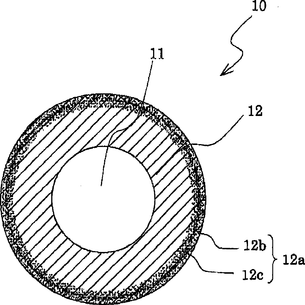
The invention relates to a conductive rubber member. The invention provides a conductive rubber member that is free from the problem of pollution and leakage like OPC and the like and that has following-up property with respect to deformation and small variation of resistance value. The conductive rubber member is a conductive rubber member provided with a surface processing layer 12a that is formed by immersing a surface layer portion of an outmost conductive elastic layer 12 endowed with conductivity in a surface processing solution at least comprising isocyanate components and organic solvents, the upper portion 12b at the surface side of the surface processing layer 12a has a density of the isocyanate components therein which is greater than that on the surface side, and the lower portion 12c at the lower side of the upper portion 12b has a density of the isocyanate components that gradually decreases inwardly.

Description

[technical field] [0001] The present invention relates to a charging roller, a transfer roller, a developing roller, a toner supply roller, a cleaning roller, etc. which are particularly suitable for use in image forming devices such as electrophotographic copiers and printers, or inkjet copiers and printers. Conductive rollers, cleaning blades (cleaning blades), conductive rubber members such as transfer belts. [Background technique] [0002] The conductive rubber roller, which controls the conductivity after having rubber elasticity, is very important in the electrophotographic process, and the molecules constituting the rubber themselves rarely have the resistivity necessary for the process (10 4 ~10 9 Ωcm), only a limited number of substances such as epichlorohydrin have found practical use. In many cases, in order to maintain the required elastic modulus, mechanical strength, and temperature and humidity characteristics, conductive particles such as carbon black are a...

Claims


Application Information

Patent Timeline
IPC IPC(8): C08J7/12G03G15/08G03G15/00
Inventor 平川直树土岐麻实
Owner SYNZTEC
Learn More