Manufacture equipment of rainbow tube

A manufacturing equipment, rainbow technology, applied in the field of rainbow tube manufacturing equipment, can solve problems such as reducing production efficiency

Inactive Publication Date: 2009-04-01
温州岳虹塑料机械有限公司
View PDF2 Cites 1 Cited by
  • Summary
  • Abstract
  • Description
  • Claims
  • Application Information

AI Technical Summary

Problems solved by technology

[0005] This kind of die head structure of the present invention, because its two diversion passages form an included angle on the mold core, namely each diversion passage is arranged obliquely on the mold core, therefore, after the plastic is extruded by the screw, after passing through the discharge port When entering the mold core, it will flow down the slope of the distribution channel, without accumulation and forming a dead angle. Therefore, to a large extent, the problem of reducing production efficiency due to blockage of the channel in the die head is solved, and the rainbow tube is extruded smoothly. , which improves the production quality of the rainbow tube; and after the support shaft and the hob shaft of the knurling mechanism are connected with the first screw and the second screw, an adjustable mechanism is formed, so that after the rainbow tube is knurled, the texture depth is consistent, and the texture Clear, so that the astigmatism performance of the knurled rainbow tube has been greatly improved; the setting of the two-layer water tank enables the extruded rainbow tube to circulate and cool, improving the cooling effect; the screw in the extrusion mechanism With this structure, the mixing effect is good, the energy consumption is reduced, the pressure is reduced, the speed of the screw is increased, and the output is increased at the same time; the setting of the thread and nut at the tail of the self-aligning shaft can make the core Moves within the barrel to control the amount of plastic extruded in the die

Method used


Image

  • Manufacture equipment of rainbow tube
  • Manufacture equipment of rainbow tube
  • Manufacture equipment of rainbow tube

Examples


Embodiment Construction

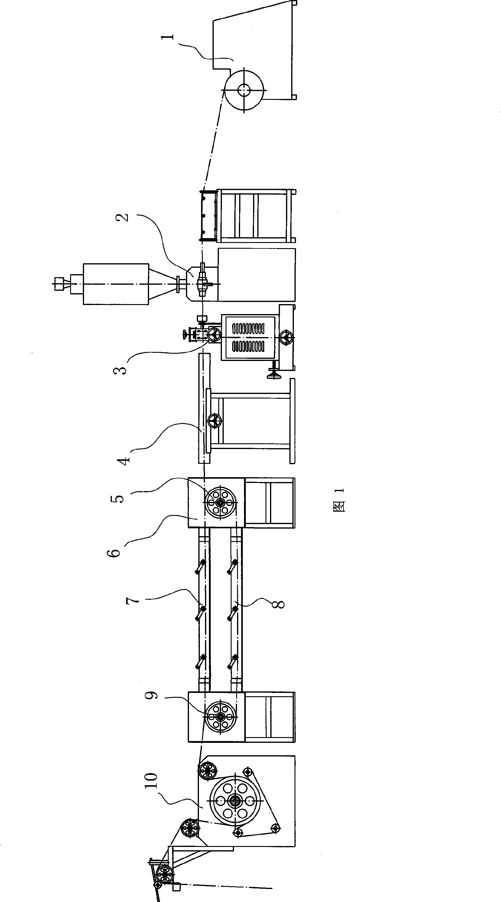
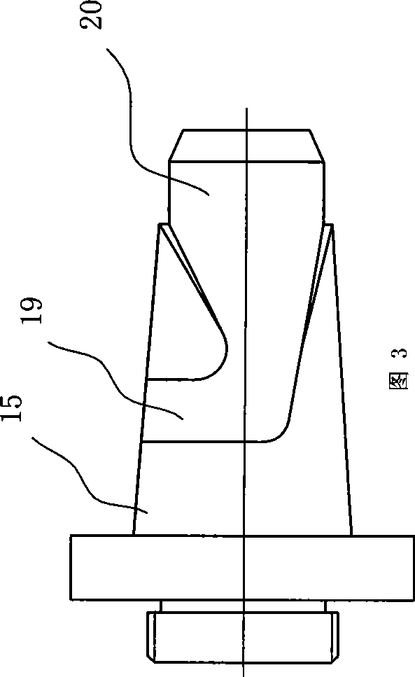
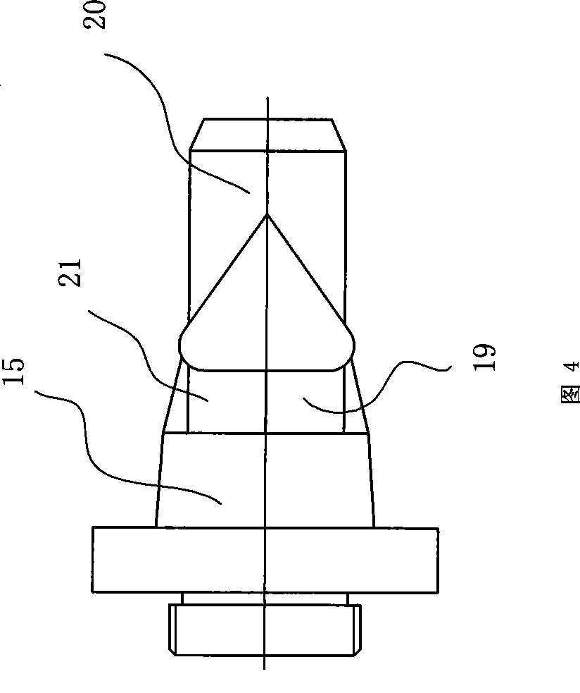
[0014] With reference to the accompanying drawings, the manufacturing equipment of this rainbow tube includes a discharge mechanism 1, an extrusion mechanism 2, a knurl mechanism 3, a cutting mechanism (not shown in the figure), two cooling mechanisms 4, 6 and a traction mechanism 10 , the cutting mechanism is installed on the traction mechanism 10. After the cutting mechanism of the present invention is installed on the traction mechanism 10, its cutting knife can be lifted or lowered according to the needs, depending on the needs of the work, which belongs to the prior art. In this paper No longer. Wherein, the discharge mechanism 1, extrusion mechanism 2, knurling mechanism 3, cooling mechanism 4, 6 and traction mechanism 10 are placed in sequence, and the extrusion mechanism 2 is composed of a barrel (not shown in the figure), a screw 25 and a die head, the die head includes an aligning shaft 12, a mold core 15, a mold barrel 16, an inner core positioning die 17 and a die ...


PUM


Abstract

The invention discloses manufacturing equipment of a rainbow tube, which is primarily characterized in that: a die head comprises an aligning shaft (12), a die core (15), a die barrel (16), inner core positioning dies (17) and dies (18), wherein, the die core is sheathed on the aligning shaft and sheathed into the die barrel, the inner core positioning dies are installed on the die core detachably, the dies are installed on the core barrel detachably, the die barrel is connected and communicated with a feed barrel of an extruder through a discharge port, two diffluent channels (19 and 21) are arranged on the die core, an included angle is formed by the two diffluent channels, the entry ends of the two diffluent channels are connected and communicated with the feed barrel through a through hole and the discharge port on the die barrel, and the exit ends of the two diffluent channels are connected and communicated with the channels of the dies. The inner core and outer sheath of the rainbow tube can be completed together on a set of equipment only by changing the inner core positioning dies and dies with different calibers as the detachable inner core positioning dies and dies are adopted, furthermore, plastics are not easy to stack in the die head, thus being characterized by quick discharge and high production efficiency.

Description

technical field [0001] The invention relates to a manufacturing device of a rainbow tube, in particular to a manufacturing device of a neon tube. Background technique [0002] Usually, the production of neon lights has the following steps: first, the plastic is extruded out of the die through the extruder, and at the same time, the copper wire is threaded in the die. At this time, what is extruded from the die is a copper wire Inner core, then cut the inner core, connect the LED tube to the copper wire, then pass the inner core through the die, and form a plastic tube with a larger diameter together with the plastic extruded from the die, after rolling The knurled pattern of the flower machine makes the light emitted by the LED tube diffuse, and finally after cooling, it becomes a neon light, which is also called a rainbow tube. And the machinery of making this rainbow tube also basically is made of feeding mechanism, extruding mechanism, knurling mechanism, cooling mechani...

Claims


Application Information

Patent Timeline
Patent Type & Authority Applications(China)
IPC IPC(8): F21S4/00H01L33/00F21Y101/02F21S4/26F21Y115/10
Inventor 谢阿洪
Owner 温州岳虹塑料机械有限公司
Why Eureka
Try Eureka