Ultrasonic flowmeter

An ultrasonic and flowmeter technology, which is used in the measurement of flow/mass flow, liquid/fluid solid measurement, measurement devices, etc., and can solve problems such as long periods of time.

Inactive Publication Date: 2012-06-13
TOKYO KEISO
View PDF2 Cites 0 Cited by
  • Summary
  • Abstract
  • Description
  • Claims
  • Application Information

AI Technical Summary

Problems solved by technology

When this calculation is performed by software, a long period of time is required, and when this calculation is performed by hardware, it is necessary to use a high-performance expensive signal processing unit

Method used


Image

  • Ultrasonic flowmeter
  • Ultrasonic flowmeter
  • Ultrasonic flowmeter

Examples


Embodiment Construction

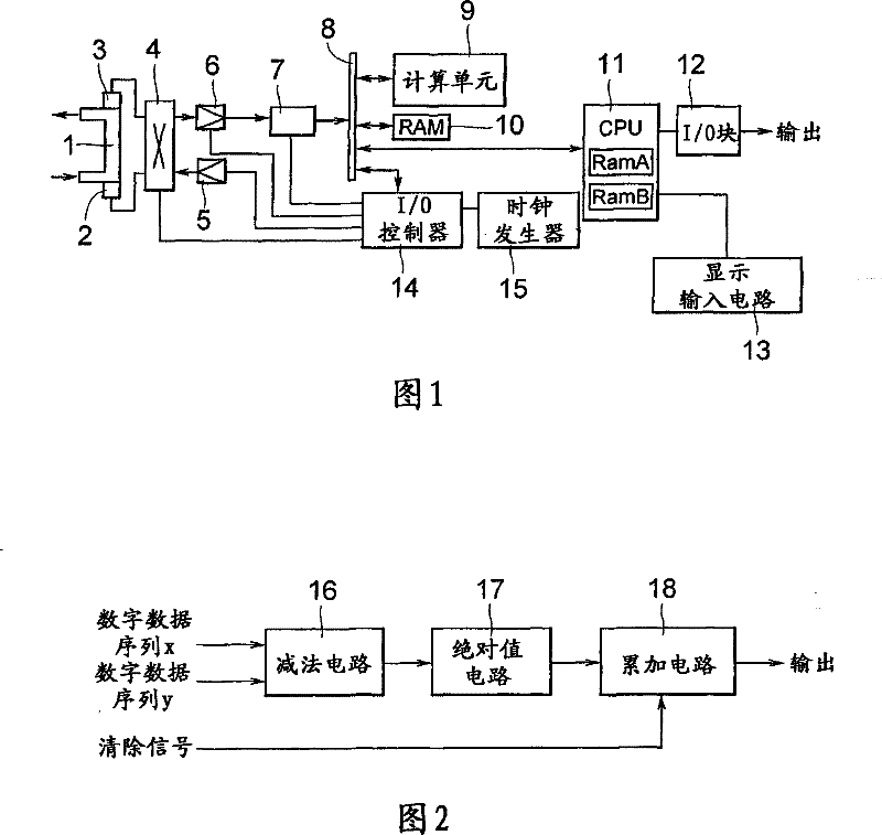
[0035] figure 1 is a block diagram showing an embodiment of an ultrasonic flowmeter according to the present invention. The fluid whose flow is to be measured flows through conduit 1 . At upstream and downstream positions of the catheter 1, ultrasonic vibrating elements 2 and 3 are provided, respectively. It should be noted that the ultrasonic element 2 is used to transmit ultrasonic waves and receive ultrasonic waves transmitted from the ultrasonic vibrating element 3 , and similarly, the ultrasonic vibrating element 3 is used to transmit ultrasonic waves and receive ultrasonic waves transmitted from the ultrasonic vibrating element 2 .

[0036] The ultrasonic vibrating elements 2 and 3 are selectively connected to a transmission amplifier 5 and a reception variable gain amplifier 6 via a converter or a multiplexer 4 . The output of the receiving variable gain amplifier 6 is connected to the computing unit 9 , RAM 10 and CPU 11 via the A / D converter 7 and the data bus 8 . ...


PUM


Abstract

The invention provides an ultrasonic flowmeter; the ultrasonic flowmeter measures the flux of the fluid which passes by a conduit by detecting the difference of travel time between a forward travel time that the ultrasonic travels in the forward direction in the conduit and a backward travel time that the ultrasonic travels in the backward direction in the conduit; the forward ultrasonic signal and the backward ultrasonic signal generated by an ultrasonic vibration element are sampled, thus working out the forward digital data sequence x and the backward digital data sequence y; x and y are memorized in a memory; the forward digital data sequence x and the backward digital data sequence y are read out through a first memory and a second memory; the sum of the absolute difference value of the forward digital data sequence x and the backward digital data sequence y is calculated; simultaneously, the data position of the forward digital data sequence x and the backward digital data sequence y are relatively offset; the offset quantity of the data position where the sum of the absolute difference value is minimum is detected; the travel time difference of the ultrasonic is calculated according to the detected offset quantity of the data position, thus working out the flowing speed of the fluid in the conduit according to the travel time difference of the ultrasonic; furthermore, the flux of the fluid which passes by the conduit is worked out according to the flowing speed and the known cross-section area of the conduit.

Description

technical field [0001] The present invention relates to an ultrasonic flow meter for measuring the flow of fluid flowing through a conduit using ultrasonic waves. Background technique [0002] In known ultrasonic flowmeters for measuring the flow of fluid flowing through a conduit, an ultrasonic pulse is sent within the conduit from an upstream position to a downstream position to detect the forward transit time of the ultrasonic pulse, from a downstream position within the conduit upwards Send the ultrasonic pulse at the upstream position to detect the backward transmission time of the ultrasonic pulse, then detect the difference between the forward transmission time and the backward transmission time to obtain the transmission time difference, and finally measure the transmission time difference from the detected ultrasonic pulse fluid flow. [0003] A known ultrasonic flowmeter is disclosed in Japanese Patent Application Laid-Open No. 2002-162269, in which the ultrasonic...

Claims


Application Information

Patent Timeline
Patent Type & Authority Patents(China)
IPC IPC(8): G01F1/66
Inventor 杉时夫佐佐木唯夫
Owner TOKYO KEISO
Why Eureka
Try Eureka