Abrasion test method of air valve and seat ring

A wear test and valve technology, applied in the field of power machinery, can solve the problems of inconvenient data sorting and regular exploration, unfavorable progress and cycle control, accuracy and precision effects, etc., to improve reliability, shorten test time, and improve accuracy. degree of effect

Inactive Publication Date: 2009-04-01
ZHEJIANG UNIV
View PDF0 Cites 19 Cited by
  • Summary
  • Abstract
  • Description
  • Claims
  • Application Information

AI Technical Summary

Problems solved by technology

[0003]Traditional valve and seat test and evaluation methods at home and abroad are usually carried out on the complete engine, which not only has a long cycle, high cost, and manpower loss, but also suffers from Environmental factors and other influences are relatively large, and it is not convenient to organize data and explore rules. The traditional limitation of valve seating speed is often limited by empirical values.
In addition to this test evaluation method, some scholars and manufacturers use the original cam drive or cam-rocker mechanism to drive the valve for test and evaluation, but this will virtually produce an additional friction pair or cam-valve pair of cam and valve seat ring. The new wear between the rocker arm and the rocker arm-valve seat ring two pairs of friction pairs, while evaluating one pair of friction pairs, sacrifices the other pair or two pairs of friction pairs, which will also affect the accuracy of the test results and evaluation methods and have some detrimental effects on the accuracy
And due to the limitation of the cam profile, even through the adjustment of the valve clearance, the seating speed of the valve is relatively limited, which is not conducive to the progress and cycle control of the test

Method used


Image

  • Abrasion test method of air valve and seat ring
  • Abrasion test method of air valve and seat ring
  • Abrasion test method of air valve and seat ring

Examples


Embodiment Construction

[0029] The present invention will be described in further detail below in conjunction with the accompanying drawings, but not as a limitation of the present invention.

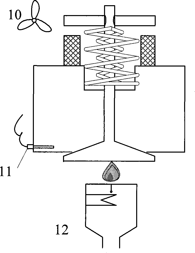
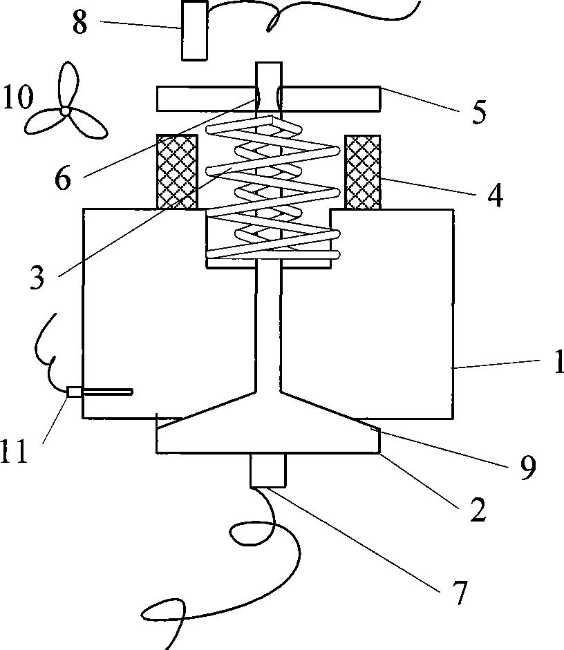
[0030] like figure 1 , 2 As shown, the new valve and seat ring wear test system diagram is divided into test state and calibration state state diagram. It includes: cylinder head 1, valve 2, valve spring 3, electromagnet 4, spring seat 5, valve lock clip 6, valve acceleration sensor 7, spring seat displacement sensor 8, valve seat 9, electromagnet cooling fan 10 , the cylinder head temperature sensor 11, the burner 12, the valve 2 is located on the cylinder head 1, the cylinder head temperature sensor 11 is installed on the cylinder head 1, one end of the valve spring 3 is supported on the cylinder head 1, and the other end is pressed against the spring seat ring 5 Above, the spring retainer 5 is fixed on the valve 2 with the valve lock clip 6, the electromagnet 4 is installed on the cylinder head 1, and is ...


PUM


Abstract

The invention relates to a quick abrasion testing method in the field of power machinery technique, aiming at providing an abrasion testing method used for a valve and a seat ring which are used for an internal-combustion engine. The method comprises a calibration stage and a test stage; in the calibration stage, a valve base is provided with a valve acceleration sensor; a displacement sensor is arranged above a valve spring seat ring; an electromagnet coil gets the electricity; an upper bit machine records the dripping speed and distance of the valve and determines the power-on control strategy for the electromagnet; during the test stage, the valve is heated by an installed burner; and the upper bit machine determines the rotation speed control strategy of the cooling water pump of a water cooling system. The quick abrasion testing method can achieve extremely high impact frequency, and shorten the testing time; the dripping speed of the valve can be jointly determined by two different sensors and the accuracy of the test is improved; the temperature of the cylinder cover is kept at the temperature of the cylinder cover when the internal combustion machine works normally, thus ensuring the reliability of the testing conclusion. The parts are few, the structure is simple and the manufacture cost is low.

Description

technical field [0001] The invention relates to a rapid wear test method in the technical field of power machinery, more specifically, the invention relates to a wear test method of a valve and a seat ring for an internal combustion engine. Background technique [0002] The valve and the seat ring are one of the important friction pairs of the engine. They work under the condition of high temperature and impact, and at the same time, there is exhaust gas corrosion. The working conditions are harsh, and they are prone to wear and failure. The operating life and reliability of valves and seat rings determine the working performance, service life and output power of the engine to some extent. Especially in recent years, as the power and reliability requirements of engines, especially diesel engines, have increased, the requirements for the friction pair of valves and seat rings have also increased accordingly. In recent years, with the deepening of research on the wear mechani...

Claims


Application Information

Patent Timeline
Patent Type & Authority Applications(China)
IPC IPC(8): G01N3/38G01N3/56
Inventor 李佳刘忠民俞小莉
Owner ZHEJIANG UNIV
Why Eureka
Try Eureka