Cyclone separator

A technology of cyclone separator and cyclone, which is applied in the direction of separation method, dispersed particle separation, cyclone device, etc., can solve the problems of central tube rupture and thermal stress load increase

Active Publication Date: 2009-04-01
FLSMIDTH AS
View PDF1 Cites 3 Cited by
  • Summary
  • Abstract
  • Description
  • Claims
  • Application Information

AI Technical Summary

Problems solved by technology

Radial temperature gradients of this magnitude in the support greatly increase thermal stress loads which, in unfavorable c

Method used


Image

  • Cyclone separator
  • Cyclone separator

Examples


Embodiment Construction

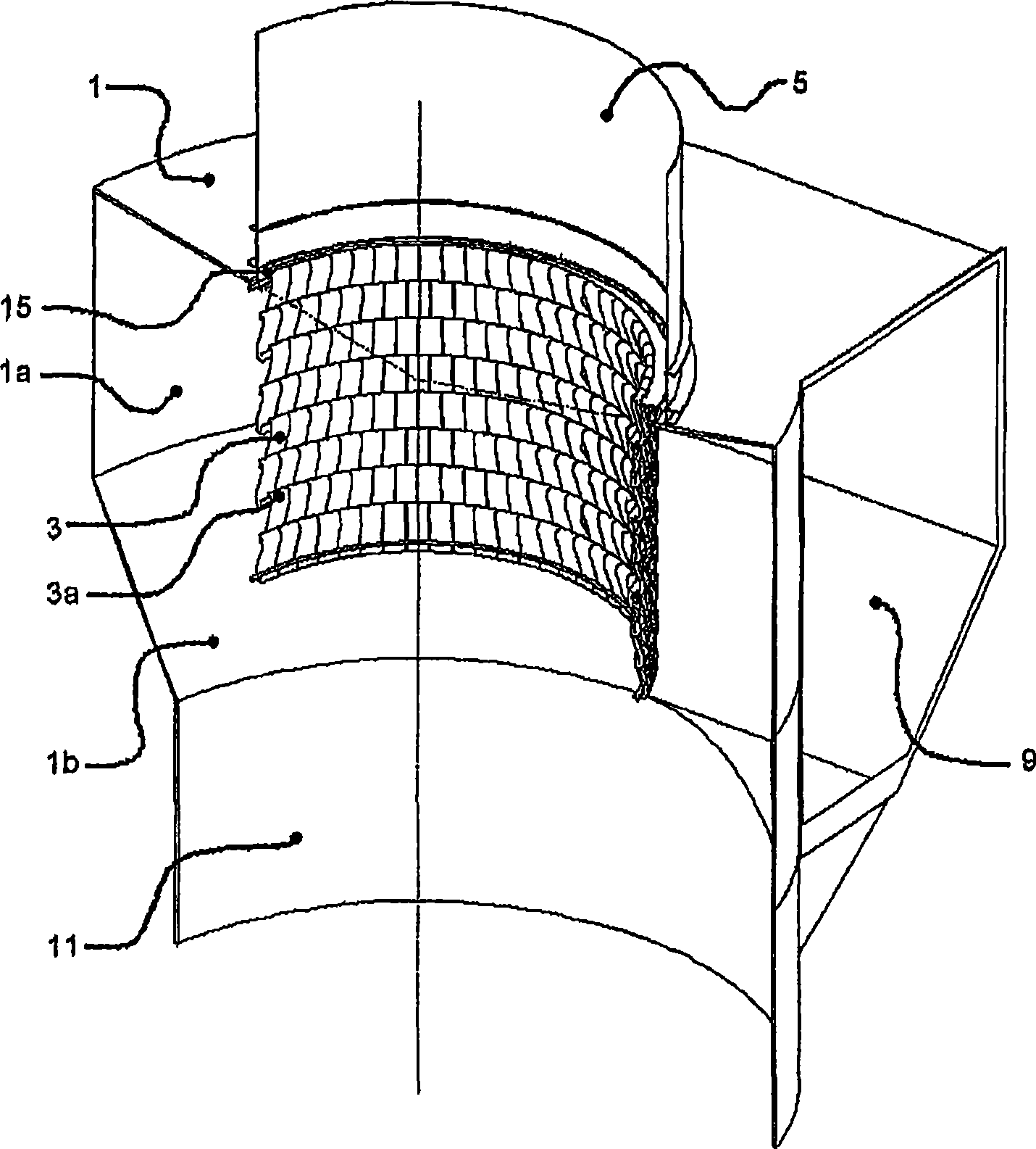
[0016] exist figure 1 It can be seen in FIG. 2 that the cyclone separator comprises a cyclone housing 1 . The cyclone housing 1 has: an upper cylindrical part 1a and a lower conical part 1b; a tangential inlet 9 for introducing the suspension to be separated; an outlet 11 at the bottom of this conical part for diverting a part of the suspension and a central pipe 3 that projects axially into the cyclone housing 1 for diverting the second portion of the suspension via a discharge pipe 5 .

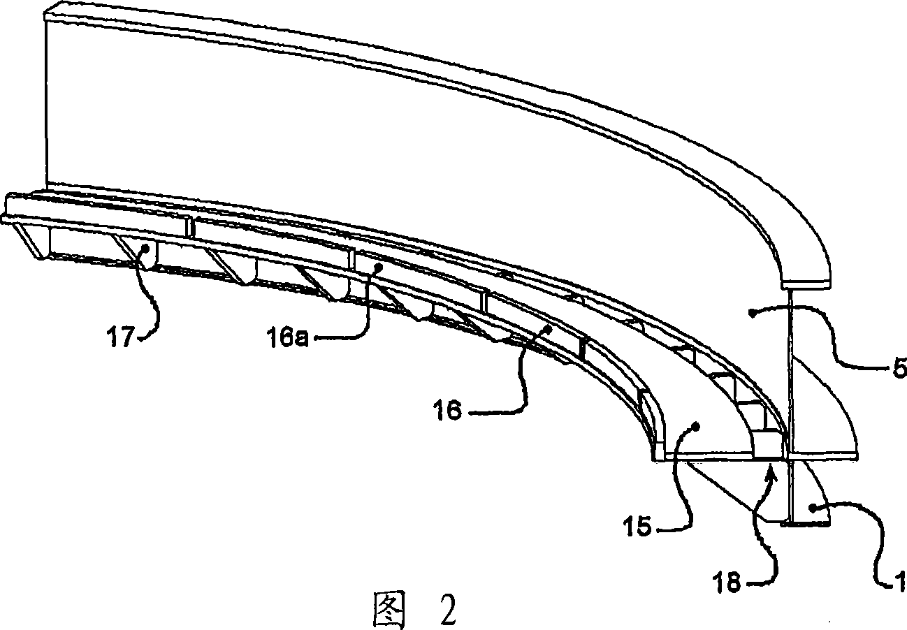
[0017] The central pipe 3 consists of a plurality of sections 3 a which are suspended from a support 15 at the upper end of the cyclone housing 1 . The support 15 comprises an upwardly projecting flange 16 which, as shown, is divided into a plurality of segments 16a.

[0018] According to the invention, the cyclone comprises a plurality of conveying means 17 , shown here as triangular brackets 17 , fixed to and evenly distributed on the innermost part of the discharge pipe 5 . A support i...


PUM


Abstract

Described is a cyclone separator comprising a cyclone housing (1), a discharge duct (5) and a central tube (3) for diverting gases, said central tube (3) extends axially into the cyclone housing (1) and being composed by a number of segments (3a) which are suspended on a supporting element (15) provided in the area between the cyclone housing (1) and the discharge duct (5). The cyclone separator is peculiar in that it comprises a number of carrying means (17) which are evenly distributed and fixed to the inner side of the cyclone housing (1) and/or the discharge duct (5), and in that the supporting element (15) comprises an annular disc which is loosely fitted on top of the carrying means (17) and having an outer diameter which is smaller than the inner diameter of the cyclone housing (1) and/or the discharge duct (5) so that a clearance (18) is provided between the annular disc (15) and the cyclone housing (1) and/or the discharge duct (5). Hereby is obtained a significant reduction in the heat transmission from the supporting element to the cyclone housing and/or the discharge duct so that the radial temperature gradient in the supporting element is reduced with an approximately uniform temperature over the radial cross section of the element. Hence the thermal stresses in the supporting element will be substantially reduced. This is mainly ascribable to the reduction in the contact area between the supporting element and the cyclone housing and/or the discharge duct.

Description

technical field [0001] The invention relates to a cyclone separator, comprising a cyclone shell, a discharge pipe and a central pipe for diverting gas, said central pipe axially protruding into the cyclone shell and suspended by a plurality of The section on the support in the area between the body and the discharge pipe is formed. Background technique [0002] Cyclone separators are well known and widely used in many different technical applications for separating two phases of a suspension, eg gas and material particles. A cyclone generally comprises: a cyclone housing with an upper substantially cylindrical part and a lower conical part; a tangential inlet for introducing the suspension to be separated on the upper part of the cyclone housing; The bottom of the conical portion serves as an outlet for diverting a portion of the suspension; and a central pipe, the free end of which extends axially into the cyclone housing, for diverting the first flow of the suspension via...

Claims


Application Information

Patent Timeline
IPC IPC(8): B04C5/181B04C5/13B04C5/14
CPCB04C5/13F27D13/00F27B7/2016B04C5/12B01D45/12
Inventor 莫滕·K·汉森
Owner FLSMIDTH AS
Why Eureka
Try Eureka