Burner for growing crystals by flame fusion method

A technology for growing crystals and burners, applied in the directions of single crystal growth, crystal growth, single crystal growth, etc., can solve the problems of increasing crystal oxygen vacancies, uneven crystal composition, and high local temperature, to improve size and uniformity, reduce Crystal oxygen vacancies and the effect of improving crystal quality

Pending Publication Date: 2018-07-13
SHENYANG INST OF ENG
View PDF4 Cites 0 Cited by
  • Summary
  • Abstract
  • Description
  • Claims
  • Application Information

AI Technical Summary

Problems solved by technology

The disadvantage of this two-tube burner lies in three aspects: first, the flame provided is concentrated on the top of the melting cap, and the radial temperature gradient of the melting cap is large, which makes it difficult to grow crystals with broad shoulders, and it is not easy to grow into large-sized crystals. It is not possible to reduce the radial temperature gradient by reducing the diameter of the central nozzle, because after the diameter of the central nozzle is increased, the flow of oxygen must be maintained to prevent tempering, causing the calorific value to exceed the requirement and causing the local temperature to be too high; secondly, too concentrated airflow As a result, there is a large gradient in the axial and radial pressure distribution around the melt in the furnace, resulting in uneven composition of the grown crystal and affecting the quality of the crystal; finally, because some oxide crystal growth defects largely depend on the oxygen vacancies in the crystal , such as yttrium lutetium silicate crystal, if the oxygen distribution is uneven or the oxygen-deficient environment will increase the crystal oxygen vacancies, seriously affecting the optical properties of the crystal

Method used


Image

  • Burner for growing crystals by flame fusion method

Examples


Embodiment 1

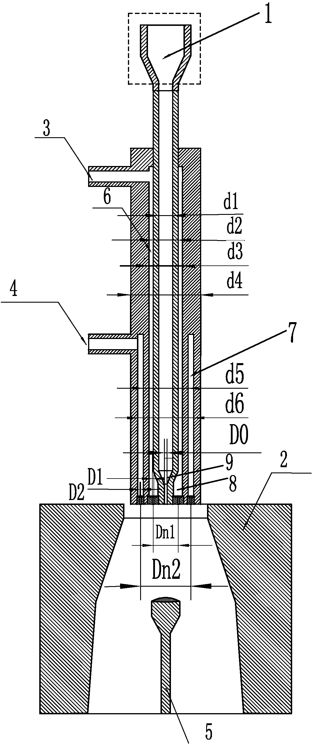
[0025] Embodiment 1, a kind of burner of growing crystal by flame melting method, see figure 1 In this embodiment, the burner is located in the middle of the three-stage frustum-shaped structure, and has a cylindrical structure as a whole, including: a conical feeding port 1, a central pipe, a hydrogen inlet 3, an external oxygen inlet 4, a hydrogen annular pipeline 6, and an external oxygen annular Pipeline 7, crystal growth chamber 2 and crystal growth base 5, the tapered feeding port 1 is connected to the central tube, powder and oxygen are fed into the central tube from the tapered feeding port 1, and a hydrogen annular pipeline is arranged outside the central tube 6. The hydrogen ring pipeline 6 is filled with hydrogen through the hydrogen gas inlet 3 connected to it, and the outer oxygen ring pipeline 7 is arranged outside the hydrogen gas ring pipeline 6, and the outer oxygen ring pipeline 7 is filled with oxygen through the external oxygen inlet 4 connected thereto. , ...

Embodiment 2

[0031] Embodiment 2, differs from Embodiment 1 of the present invention in that: wherein: the inner diameter d1 of the central tube is 8.2mm, the inner diameter d2 of the hydrogen annular pipeline is 21.5mm, the outer diameter d3 of the hydrogen annular pipeline is 36mm, and the outer oxygen annular The inner diameter d5 of the pipeline is 38mm, the outer diameter d6 of the external oxygen annular pipeline is 43mm, the outer wall diameter d4 of the burner is 54.3mm, the diameter D0 of the central tube nozzle is 3.5mm, and the diameter D0 of the central tube nozzle is determined according to the crystal to be prepared. The hydrogen annular pipeline nozzle is 12 circular holes with equal diameters, and the centers of the 12 circular holes are connected to each other to form a hydrogen annular pipeline nozzle distribution circle. The hole diameter D1 is 2mm, and the nozzle of the external oxygen annular pipeline is 12 circular holes with equal diameters, the centers of the 12 circ...

Embodiment 3

[0033] Embodiment 3 is different from Embodiment 1 of the present invention in that: the inner diameter d1 of the central tube is 6mm, the inner diameter d2 of the hydrogen annular pipeline is 14mm, the outer diameter d3 of the hydrogen annular pipeline is 23mm, and the inner diameter d5 of the outer oxygen annular pipeline The outer diameter d6 of the external oxygen annular pipe is 36mm, the outer wall diameter d4 of the burner is 48mm, the diameter D0 of the central tube nozzle is 3.0mm, and the diameter D0 of the central tube nozzle is determined according to the crystal to be prepared. The hydrogen annular pipeline nozzle is 15 circular holes with equal diameters, and the centers of the 15 circular holes are connected to each other to form a hydrogen annular pipeline nozzle distribution circle. The hole diameter D1 is 0.5mm, and the nozzle of the external oxygen annular pipeline is 15 circular holes with equal diameters. The centers of the 15 circular holes are connected w...


PUM

PropertyMeasurementUnit
diameteraaaaaaaaaa
lengthaaaaaaaaaa
diameteraaaaaaaaaa

Abstract

The invention discloses a burner for growing crystals by a flame fusion method. The burner comprises a conical feeding port, a central pipe, a hydrogen inlet, an external oxygen inlet, a hydrogen ring-shaped pipeline, an external oxygen ring-shaped pipeline, a crystal growing chamber and a crystal growing base, wherein the conical feeding port is connected with the central pipe; powder and oxygenare fed into the central pipe from the conical feeding port; the central pipe is externally provided with the hydrogen ring-shaped pipeline; hydrogen is filled into the hydrogen ring-shaped pipeline by the hydrogen inlet connected with the hydrogen ring-shaped pipeline; the hydrogen ring-shaped pipeline is externally provided with the external oxygen ring-shaped pipeline; oxygen is filled into theexternal oxygen ring-shaped pipeline by the external oxygen inlet connected with the external oxygen ring-shaped pipeline; the tail ends of the central pipe, the hydrogen ring-shaped pipeline and theexternal oxygen ring-shaped pipeline are respectively communicated with the crystal growing chamber; the crystal growing base is arranged in the growing chamber. The burner disclosed by the inventionhas the advantages that the radial and axial pressure distribution of the burner can be greatly reduced, so that the radial distribution of the oxygen is more uniform, oxygen vacancy of the crystal is reduced, the size and the uniformity of crystal growth are improved and the crystal quality is improved.

Description

technical field [0001] The invention belongs to the technical field of crystal material research, in particular to a burner for growing crystals by a flame fusion method. Background technique [0002] The traditional flame fusion crystal growth burners are two-tube burners. The height of the furnace body is 250mm, the outer diameter is 180mm, the inner cavity of the furnace is a truncated cone, the upper diameter is 40mm, and the lower diameter is 60mm. The refractory layer in the furnace body is made of corundum powder and clay, the insulation layer is filled with asbestos, and the outer wall is a cylinder made of 1mm thick steel plate. The diameter of the central hole is 4mm, which is used to feed oxygen and oxide powder, and 12 hydrogen holes with a diameter of 2mm are evenly distributed on a circle with a diameter of 18mm. When working, oxygen and oxide powder enter the combustion chamber from the upper part, and the oxygen and the hydrogen fed into the external tube a...

Claims


Application Information

Patent Timeline
Patent Type & Authority Applications(China)
IPC IPC(8): C30B11/00C30B29/34
CPCC30B11/003C30B29/34
Inventor 周文平毕孝国刘旭东蔡云平唐坚孙旭东
Owner SHENYANG INST OF ENG
Why Eureka
Try Eureka