A catalytic conversion stripper

A catalytic conversion and stripper technology, applied in catalytic cracking, chemical instruments and methods, cracking, etc., can solve the problem of low stripping efficiency, improve contact efficiency and mass transfer efficiency, wide application range, and increase circulation Effect

Active Publication Date: 2011-12-07
SINOPEC LUOYANG PETROCHEM ENG CORP
View PDF7 Cites 1 Cited by
  • Summary
  • Abstract
  • Description
  • Claims
  • Application Information

AI Technical Summary

Problems solved by technology

[0008] The purpose of this invention is to provide a kind of catalytic conversion stripper, to solve the problem that the stripping efficiency of existing catalytic conversion stripper is not high

Method used


Image

  • A catalytic conversion stripper
  • A catalytic conversion stripper
  • A catalytic conversion stripper

Examples


Embodiment Construction

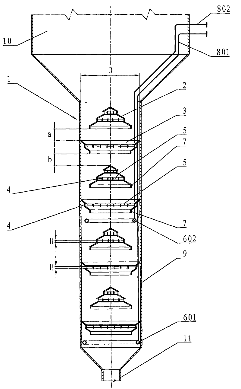
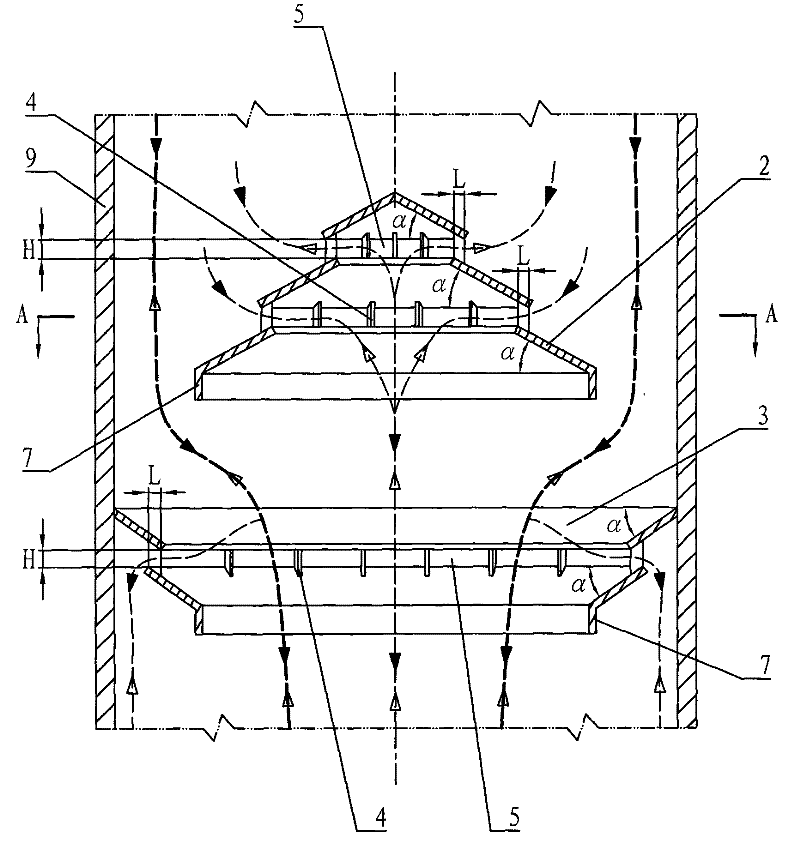
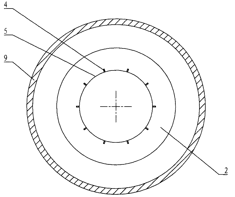
[0025] see figure 1A catalytic reforming stripper 1 of the present invention is shown. This catalytic conversion stripper is a kind of external riser type catalytic conversion stripper (the riser reactor of the catalytic conversion device is located outside the catalytic conversion stripper, figure 1 Not shown in ), used as a settler stripper of a catalytic converter, for stripping spent catalyst entrained with oil gas from the settler. The catalytic conversion stripper is referred to as the stripper for short. figure 1 The shown stripper 1 is arranged below the settler 10, and the stripper 1 includes a cylinder 9, and the cylinder 9 is provided with a stripping steam distributor and a group of stripping baffles. The top of the cylinder 9 is connected to the bottom of the settler 10; the bottom of the cylinder 9 is provided with a head (generally a hemispherical head or a conical head), and the bottom of the head is provided with a standpipe or inclined pipe 11 , connected ...


PUM


Abstract

The invention discloses a catalytic conversion stripper used in catalytic conversion devices in petroleum refining and petrochemical industries, in order to solve the problem of low stripping efficiency existing in the existing catalytic conversion strippers. In the stripper of the present invention, each set of stripping baffles is composed of a stacked inner ring stripping baffle (2) and a stacked outer ring stripping baffle (3) below it. The stacked inner ring stripping baffle (2) is composed of at least 2 single-layer inner ring stripping baffles, and the stacked outer ring stripping baffle (3) is composed of at least 2 single-layer outer ring stripping baffles. Between the upper single-layer inner-ring stripping baffle and the next single-layer inner-ring stripping baffle and between the upper single-layer outer-ring stripping baffle and the next single-layer outer-ring stripping baffle Horizontal channels (5) are formed between them. The stripper of the invention is suitable for the stripping of ungenerated catalysts entrained with oil and gas and the stripping of regenerated catalysts entrained with gas impurities in various catalytic conversion processes.

Description

technical field [0001] The invention belongs to the field of catalytic conversion reactions in petroleum refining and petrochemical industries, and relates to a catalytic conversion stripper used in a catalytic conversion device. Background technique [0002] In the fluidized catalytic cracking (FCC) settler, because the catalyst is a porous substance, the pores between the catalyst particles and the inside of the particles are full of oil and gas; this part of the oil and gas accounts for about 2w% to 4w% (w%) of the total product. Indicates the weight percentage), if the coke equivalent to an increase of 2w%-4w% is not removed, the yield of light oil is reduced. The research results of Exxon company show that if all the strippable oil and gas are stripped from the catalyst, the amount of coke will be reduced by 20w% to 40w%; the coke yield will increase due to incomplete stripping, which will increase the coke load of the regenerator ; Especially for heavy oil catalytic c...

Claims


Application Information

Patent Timeline
Patent Type & Authority Patents(China)
IPC IPC(8): B01J8/00B01J8/34C10G11/00
Inventor 张振千李国智张立新雷世远刘昱田耕乔立功马艳梅
Owner SINOPEC LUOYANG PETROCHEM ENG CORP
Why Eureka
Try Eureka