Combined type gas distributor

A gas distributor and compound technology, which is applied in the field of gas phase and gas-liquid two-phase feed distribution equipment, can solve the problems of difficult to achieve uniform distribution of gas, large amount of droplet entrainment, large airflow resistance, etc. The effect of drop, uniform radial distribution and uniform airflow

Inactive Publication Date: 2011-09-14
TIANJIN UNIV
View PDF0 Cites 1 Cited by
  • Summary
  • Abstract
  • Description
  • Claims
  • Application Information

AI Technical Summary

Problems solved by technology

For the pipe distributor, it is difficult to achieve the purpose of uniform gas distribution because the gas flows out of different openings at different rates.
However, other gas distributors have disadvantages such as large entrainment of liquid droplets in the airflow, large airflow resistance, and uneven distribution due to the existence of gas vortices above the distributor.

Method used


Image

  • Combined type gas distributor
  • Combined type gas distributor
  • Combined type gas distributor

Examples


Embodiment 1

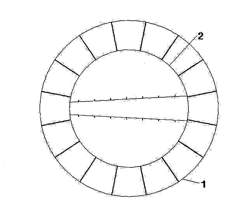
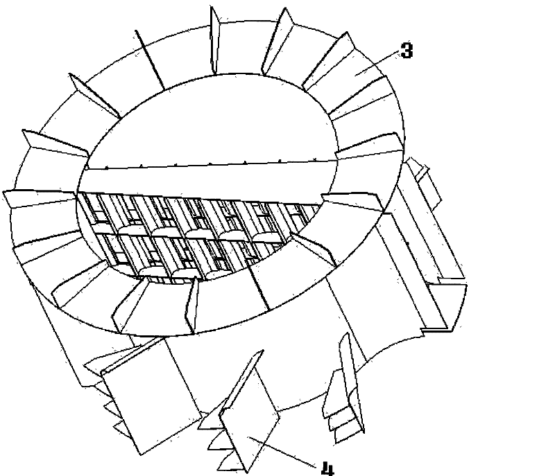
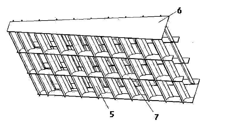
[0024] Such as figure 1 , 2 As shown, the composite gas distributor is composed of an inner cylinder 2, a top ring plate 3, a baffle plate 4, a guide vane 5, upper and lower cover plates 6 and a connecting plate 7. The size of the top ring plate 3 is determined according to the requirements of the tower wall 1 and the inner cylinder 2 . The top ring plate 3 is welded on the tower wall 1 . The inner cylinder 2 is welded to the top ring plate, so that the inner circular surface of the ring plate and the inner cylinder coincide. The double-row vane-type gas distribution device inside the inner cylinder 2 is composed of three layers connected up and down, and the guide vanes 5 in each layer are welded on the connecting plate 7 according to the corresponding positions. The whole three-layer double-row vane-type deflector and the top ring plate 3 are connected with bolts.

[0025] The baffles 4 are welded to the outside of the inner cylinder 2 according to the different position...

Embodiment 2

[0031] The basic structure of the gas distributor is the same as that of Embodiment 1. The difference from Embodiment 1 is that the hydrodynamic calculation is performed according to the specific process parameters, and the length of the baffles 4 is changed. The lengths of the four baffles are 650mm and 950mm respectively. , 1250mm, 1550mm; the internal double-row blade gas distribution structure is a single layer, with a height of 1500mm.

[0032] Process parameters:

[0033] Tower diameter: 8m, tower height: 15m, feed pipe diameter: 1.6m, feed amount: 702.5t / h, feed temperature: 90°C, feed pressure: 80mmH 2 O, feed liquid content: 0

[0034] The gas enters the distributor through the feed port and is divided into two parts, inside and outside. The gas entering the inner cylinder 2 is guided by the guide vanes 5, flows out of the double-row vane distribution device in the radial direction, and then is evenly distributed in the inner cylinder; The flow is diverted, changed...


PUM


Abstract

The invention discloses a combined type gas distributor which comprises an inner cylinder, a top ring-shaped plate and a trapezoidal double-line vane diversion device, wherein the side wall of the inner cylinder is provided with a feed inlet along the radial direction, the top ring-shaped plate is welded on the top of the inner cylinder, the trapezoidal double-line vane diversion device which hasthe cross section changed from large to small is arranged inside the inner cylinder along the direction of the feed inlet, and the double-line vane diversion device comprises a left line and a right line of at least one layer of guide vanes that are symmetrically arranged by taking a vertical axis section of the feed inlet as symmetrical plane; the upper and the lower guide vanes of the adjacent layers are connected with each other by a left and a right connecting plates, the guide vanes arranged at the top layer and the bottom layer are respectively connected with an upper and a lower cover plate, the upper and the lower cover plates as well as the left and the right connected plates are connected with the top ring-shaped plate by bolts, a plurality of whirl plates are symmetrically connected on the outer wall of the inner cylinder by taking a central section of the inner cylinder as the symmetrical plane. By changing the flow direction of gas, the combined type gas distributor achieves the aims of reducing intensity of pressure and evenly distributing the gas.

Description

technical field [0001] The invention relates to a composite gas distributor, which is a gas phase and gas-liquid two-phase feed distribution equipment of towers widely used in the chemical industry. Background technique [0002] Columns are widely used equipment in oil refining, chemical industry and other fields. With the maturity of packed tower technology, large packed towers have been gradually used in unit operations such as rectification and absorption, and the problem of uniform gas distribution in the tower has attracted more and more attention. The gas ratio of the packed tower and the performance of the gas distributor directly affect the separation efficiency and product quality of the packed tower. [0003] At present, the gas distributors widely used in industry include porous straight pipe type, straight pipe baffle type, double row blade type, tangential circulation type and so on. For the pipe distributor, it is difficult to achieve the purpose of uniform g...

Claims


Application Information

Patent Timeline
Patent Type & Authority Patents(China)
IPC IPC(8): B01J19/00B01D3/14B01D53/18
Inventor 孙津生高红王艳红任吉超田玉峰
Owner TIANJIN UNIV
Why Eureka
Try Eureka