Building shape change detecting method, and building shape change detecting system

A change detection and building technology, applied in photogrammetry/video metrology, surveying devices, surveying and navigation, etc., can solve the problems of heavy DSM load, large ortho image load, difficult processing capacity, etc., to achieve processing Effects of load reduction, data volume reduction, and immediacy improvement

Inactive Publication Date: 2009-04-08
PASUKO KK
View PDF0 Cites 16 Cited by
  • Summary
  • Abstract
  • Description
  • Claims
  • Application Information

AI Technical Summary

Problems solved by technology

[0009] However, the data volume of the digital image taken on the aircraft is very large, and on the other hand, the transmission capacity between the aircraft and the ground is relatively small
Therefore, there is a problem that it is difficult to wirelessly transmit the acquired image data directly from the aircraft to the ground
[0010] Moreover, using the method of comparing aerial images, the higher the resolution of the images, the more difficult it is to perform high-precision registration. Furthermore, the detection of changes based on the brightness information between images has the problem of low detection rate, and The problem that only changes in the plane can be detected but changes in the height direction cannot be detected
[0011] Using the method of comparing the feature points of the ortho image with the building polygon data has the problem that the load of the generation process of the ortho image is large, and it is difficult to use the limited processing capacity of the device mounted on the aircraft.
In addition, there is a problem that the change detection compared with the existing building polygon data can only detect the change of the plane
[0012] Using the method of comparing DSMs, there is a problem that the load generated by DSM is large, and it is still difficult to deal with the limited processing power of the device on board the aircraft.

Method used


Image

  • Building shape change detecting method, and building shape change detecting system
  • Building shape change detecting method, and building shape change detecting system
  • Building shape change detecting method, and building shape change detecting system

Examples


Embodiment Construction

[0040] Next, embodiments of the present invention will be described with reference to the drawings.

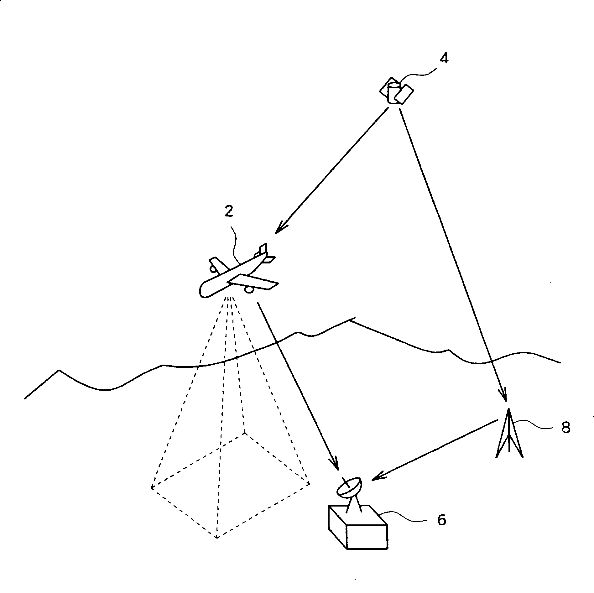
[0041] This embodiment is a building shape change detection system that detects a shape change of a building on the ground surface, and is realized using the ground shape change detection method of the present invention. For example, this system quickly grasps the collapse or abnormal movement of buildings that occur during disasters such as earthquakes, and effectively uses the information in rescue and recovery activities.

[0042] figure 1 It is a schematic diagram showing the schematic configuration of this system. The aircraft 2 is equipped with a digital camera to take images of the ground surface from above. And, the aircraft 2 is equipped with GPS / IMU (Global Positioning System / Inertial Measurement Unit), and measures and records the position and inclination of the digital camera carried on the aircraft 2 according to the signal from the GPS satellite 4 and the iner...


PUM


Abstract

There is provided a system for detecting a shape change of a building based upon an aerial photograph taken by an airplane. The system can process the aerial photograph without waiting for the airplane to land. On the airplane (2), edges are extracted directly from a central projected photographed image (S22) to be transmitted wirelessly to a ground station (6). This ground station (6) extracts segments from the edges to thereby determine a shape of the building in the photographed image. On the other hand, the ground station (6) generates a projected image of the building, which is obtained by central projecting existing three-dimensional data from a flying position of the airplane (2), and matches the projected image and the shape of the building obtained from the photographed image (S28). According to a similarity between the two through the matching, it is decided whether or not the shape of the building has changed from the time of registration of the existing three-dimensional data.

Description

technical field [0001] The invention relates to a method and system for detecting shape changes of ground objects such as buildings based on images taken from flying objects. Background technique [0002] On a flying object such as an aircraft, an image of the ground surface (aerial image) is obtained using a frame sensor type digital camera, and changes in buildings are detected from the aerial image. In recent years, based on the detection of changes in the shape of buildings using this aerial image, the subject of grasping the damage situation during disasters such as earthquakes has been studied. [0003] At present, aerial image data is stored in a data storage unit mounted on an aircraft, and after the aircraft lands, it is transferred to a data processing device on the ground for processing and analysis. The data processing device on the ground detects the change in the shape of the building by comparing and contrasting the newly obtained image of the ground surface ...

Claims


Application Information

Patent Timeline
Patent Type & Authority Applications(China)
IPC IPC(8): G01C11/00G06T1/00G06T3/00
CPCG06T2207/30184G06T7/0083G01C11/28G06T7/2053G01C11/04G06T7/2033G06T2207/10032G06T7/12G06T7/246G06T7/254G06V20/647G06V20/176
Inventor 世川正朱林
Owner PASUKO KK
Why Eureka
Try Eureka