Supercharge Your Innovation With Domain-Expert AI Agents!

Method for moving belt oil pumping machine

A technology of pumping units and belts, which is applied in the direction of machines/engines, mechanical equipment, earthwork drilling, etc., can solve the problems of insufficient moving distance and easy deviation of pumping units, etc., and achieve stable movement, fast and convenient use, and convenient manufacture Effect

Inactive Publication Date: 2009-04-15
SHENGLI OIL FIELD HIGHLAND GASOLINEEUM EQUIP
View PDF2 Cites 4 Cited by
  • Summary
  • Abstract
  • Description
  • Claims
  • Application Information

AI Technical Summary

Problems solved by technology

This device needs to drill holes on the cement foundation to fix the base. In addition, the pumping unit is easy to shift during the moving process. Due to the limitation of the length of the hydraulic cylinder, the moving distance is not enough.

Method used


Image

  • Method for moving belt oil pumping machine

Examples


Embodiment Construction

[0010] Embodiments of the present invention will be described in detail below in conjunction with the accompanying drawings.

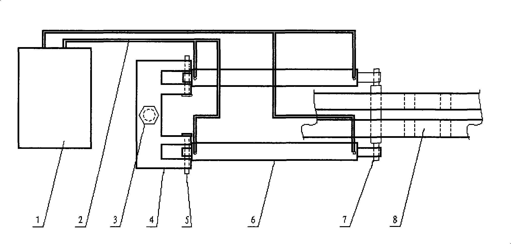
[0011] The method of moving the belt pumping unit consists of a hydraulic station 1, a high-pressure hose 2, a double-acting hydraulic cylinder 6, a hydraulic cylinder fixing seat 4, an anchor bolt 3, a pin shaft 5, and a horizontal shaft 7 for moving the machine. The hydraulic station 1 passes through The high-pressure rubber hose 2 communicates with the double-acting hydraulic cylinder 6; the hydraulic cylinder fixing seat 4 is fixed on the ground by the anchor bolt 3, one end of the two hydraulic cylinders 6 is connected with the hydraulic cylinder fixing seat 4 through the pin shaft 5, and the other end is connected with the moving machine Horizontal shaft 7 links to each other, and there are two rows or three rows of moving machine holes on pumping unit base 8, and moving machine horizontal shaft 7 is fixed on the pumping unit base 8 by moving mach...


PUM


Abstract

The invention provides a machine-shifting method for a belt pumping unit, consisting of a hydraulic station, a high pressure rubber hose, a double-acting hydraulic cylinder, a hydraulic cylinder fixing pedestal, an anchor bolt, a pin and a machine-shifting transverse axis; wherein, the hydraulic station is communicated with the double-acting hydraulic cylinder by the high pressure rubber hose, the hydraulic cylinder fixing pedestal is fixed on the ground by the anchor bolt, one end of two hydraulic cylinders are connected with the hydraulic cylinder fixing pedestal by the pin and the other ends thereof are connected with the machine-shifting transverse axis; the base of the pumping unit is provided with two or three rows of machine-shifting holes; and the machine-shifting transverse axis is fixed on the base of the pumping unit by the machine-shifting holes. The invention has the advantages of convenient manufacturing, simple structure, quick and easy use, and smooth movement.

Description

Technical field: [0001] The invention relates to a moving device for a vertical oil pumping unit, in particular to a moving method for a belt pumping unit. Background technique: [0002] In order to ensure the normal operation of the oil well, it is necessary to carry out workover operations on the oil well. Because the belt pumping unit is close to the wellhead, it affects the approach of the workover rig. In order to ensure normal workover operations, it is necessary to move the pumping unit backward for a certain distance. At present, the workover rig is mainly used to drag the pumping unit backward, and after the workover is completed, the workover rig is used to drag forward and reset. [0003] Patent 200620085474.1 discloses a shifter for a belt pumping unit. The shifter is a double cylinder. The cylinder body and the plunger are a double cylinder double plunger structure. One end of the cylinder body is equipped with a fixed plate, and the other end is provided wit...

Claims


Application Information

Patent Timeline
IPC IPC(8): F04B53/00F04B47/00E21B43/00B66F19/00
Inventor 刘明军崔凤光夏承宇王作松
Owner SHENGLI OIL FIELD HIGHLAND GASOLINEEUM EQUIP
Features
  • R&D
  • Intellectual Property
  • Life Sciences
  • Materials
  • Tech Scout
  • Unparalleled Data Quality
  • Higher Quality Content
  • 60% Fewer Hallucinations
Learn More