
Super-conduction stacking brazing method and mold for high-temperature supercurrent down-lead

A current lead and high-temperature superconducting technology, which is applied in the direction of superconducting magnets/coils, circuits, electrical components, etc., can solve the problems of loss of superconducting tape, loss of superconductivity, and fragility of HTS tape

Inactive Publication Date: 2009-04-15
INST OF PLASMA PHYSICS CHINESE ACAD OF SCI
View PDF0 Cites 20 Cited by
  • Summary
  • Abstract
  • Description
  • Claims
  • Application Information

AI Technical Summary

Problems solved by technology

Unlike the niobium-titanium alloy-based low-temperature superconducting materials with excellent mechanical properties, HTS ribbons are very fragile, and excessive bending or kink will lead to loss of superconductivity
In other words, if you accidentally lose part of the superconducting tape during the fabrication and brazing of the superconducting stack, it will cause significant economic losses.

Method used


Image

  • Super-conduction stacking brazing method and mold for high-temperature supercurrent down-lead
  • Super-conduction stacking brazing method and mold for high-temperature supercurrent down-lead

Examples


Embodiment Construction

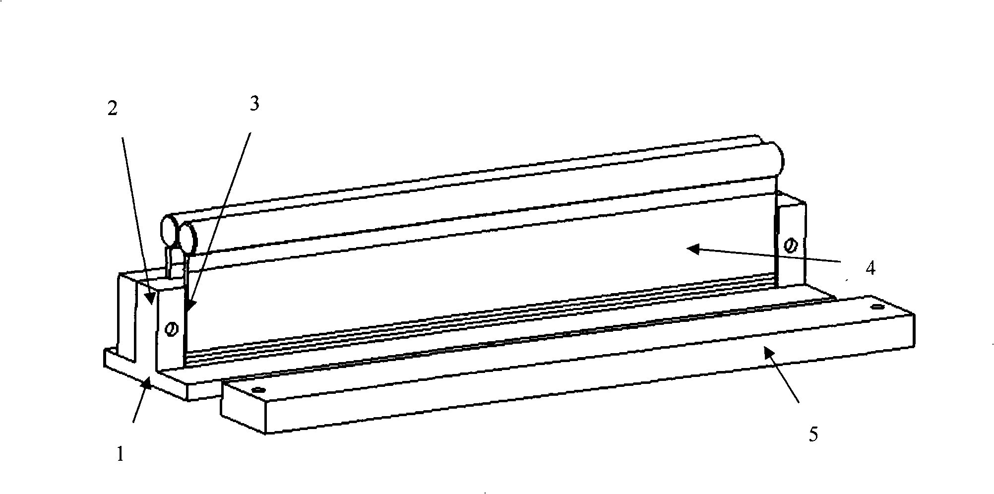
[0032] The mold used in the present invention includes a bottom plate 1 on which a middle formwork 2 is connected. The side wall of the middle template 2 has a mold groove 3 with an open side. A mold core 4 is inserted above the mold groove 3, and the thickness and width of the mold core just match the slot and are movable. A side plate 5 is covered on the outside of the mold cavity 3, and this side plate 5 is fixed on the middle template 2. The bottom plate 1, the middle formwork 3, and the bottom plate 2 are all made of hard aluminum alloy.

[0033] A copper plate is inserted between the bottom plate of the brazing mold and the flat electric furnace, and cooling water pipes are arranged on the side of the copper plate.

[0034] Prepare solder strips before soldering. Too thick solder strips will waste solder, and make excess solder squeeze out from the side, increasing the width of the stack. Therefore, the thickness of the selected solder strips should be as thin as possi...


PUM

PropertyMeasurementUnit
thicknessaaaaaaaaaa
currentaaaaaaaaaa
currentaaaaaaaaaa

Abstract

The invention discloses a superconducting stack soldering method for a high-temperature superconducting current lead wire and a mold thereof; superconducting tapes to be soldered and soldering ribbons are alternately arranged in a mold cavity which is made of metal materials with good thermal conductivity; a mold core and a counterweight are pressed on the superconducting tapes, the mold is heated to the soldering temperature under the vacuum condition, the temperature is kept for 10-15 minutes, and then the mold is rapidly cooled to the solidification point of soldering filler metals to complete the soldering. The critical current of the low-heat conductivity high-temperature superconducting tapes under a 77K self-field is only 100-120A which is much less than the thousands to tens of thousands of amperes of operating current of a large superconducting magnet, so that the superconducting tapes can be used by soldering into a stack. The price of the bismuth-based superconducting tape which takes Ag-5.3wt% Au alloy as a substrate is 5-6 times than the price of the ordinary bismuth-based superconducting tape; while the offer of a superconducting stack of foreign high-temperature superconducting companies is almost doubled again. The method and the mold for soldering the superconducting stack can ensure that the current carrying performance is not deteriorated, the longitudinal heat leakage is not increased, the soldering among the superconducting tapes is uniform and the requirements on the resistance performance in a low layer can be met.

Description

Technical field: [0001] The invention relates to a high temperature superconducting current lead stack brazing method and a mold for a large superconducting magnet. Background technique: [0002] In the 21st century, China will apply superconducting technology to high-energy accelerators, nuclear fusion experimental devices, high-field magnets and energy storage magnets on a large scale. The difficulty and high operating costs of 4K low-temperature refrigeration technology have hindered the application of low-temperature superconductivity, in which the current leads feeding large superconducting magnets are the most important heat load. The use of high temperature superconducting (HTS) current leads can reduce the 4.5K thermal load by an order of magnitude. High-temperature superconducting current leads for small superconducting magnets are commercially available, but high-current leads need to be made by themselves with low thermal conductivity Bi-2223 tape. [0003] For ...

Claims


Application Information

Patent Timeline
Patent Type & Authority Applications(China)
IPC IPC(8): H01F6/06B23K1/008B23K3/08B23K37/04
Inventor 毕延芳于景泽
Owner INST OF PLASMA PHYSICS CHINESE ACAD OF SCI
Learn More