Automated guided vehicle for rolls of newsprint

A technology for conveying vehicles and paper rolls, applied to conveyors, conveyor objects, conveyor control devices, etc., can solve the problems of high energy consumption, heavy lifting platform, difficult maintenance of rolling wheels and lifting unit 240, etc. Sex-enhancing effect

Inactive Publication Date: 2009-04-22
TSUBAKIMOTO CHAIN CO
View PDF1 Cites 15 Cited by
  • Summary
  • Abstract
  • Description
  • Claims
  • Application Information

AI Technical Summary

Problems solved by technology

Furthermore, when the height from the walking path F to the paper feeding device of the rotary printing machine is low, the height of the volume increasing platform 250 becomes an obstacle, and the unmanned conveyance vehicle 200 cannot enter under the paper feeding device of the rotary printing machine.
[0010] In addition, for the conventional unmanned transport vehicle 200, after the lifting unit 240 descends, the opening of the traveling mechanism 220 is blocked by the lifting platform 241, so it is difficult to confirm the inside of the traveling mechanism 220, for example, it is difficult to check the rolling Maintenance of wheels and lifting unit 240 etc.
In addition, the lifting platform 241 is very heavy, so the unmanned transport vehicle 200 itself will become heavier, and the energy consumption during walking and lifting is very large, and the energy efficiency is very low.

Method used


Image

  • Automated guided vehicle for rolls of newsprint
  • Automated guided vehicle for rolls of newsprint
  • Automated guided vehicle for rolls of newsprint

Examples


Embodiment Construction

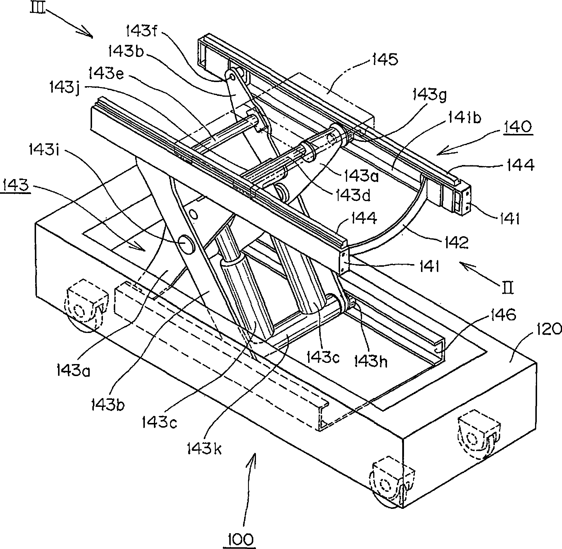
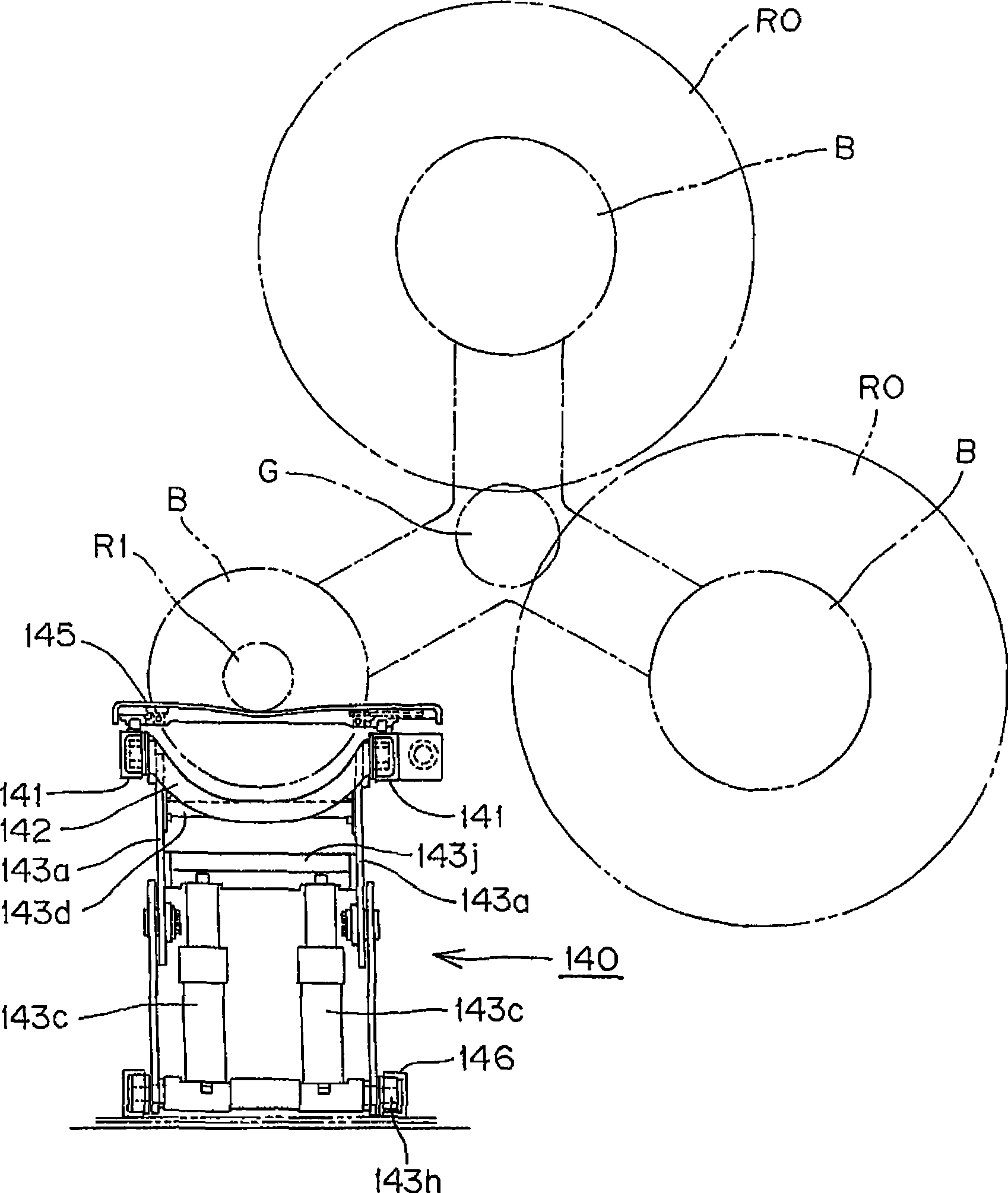
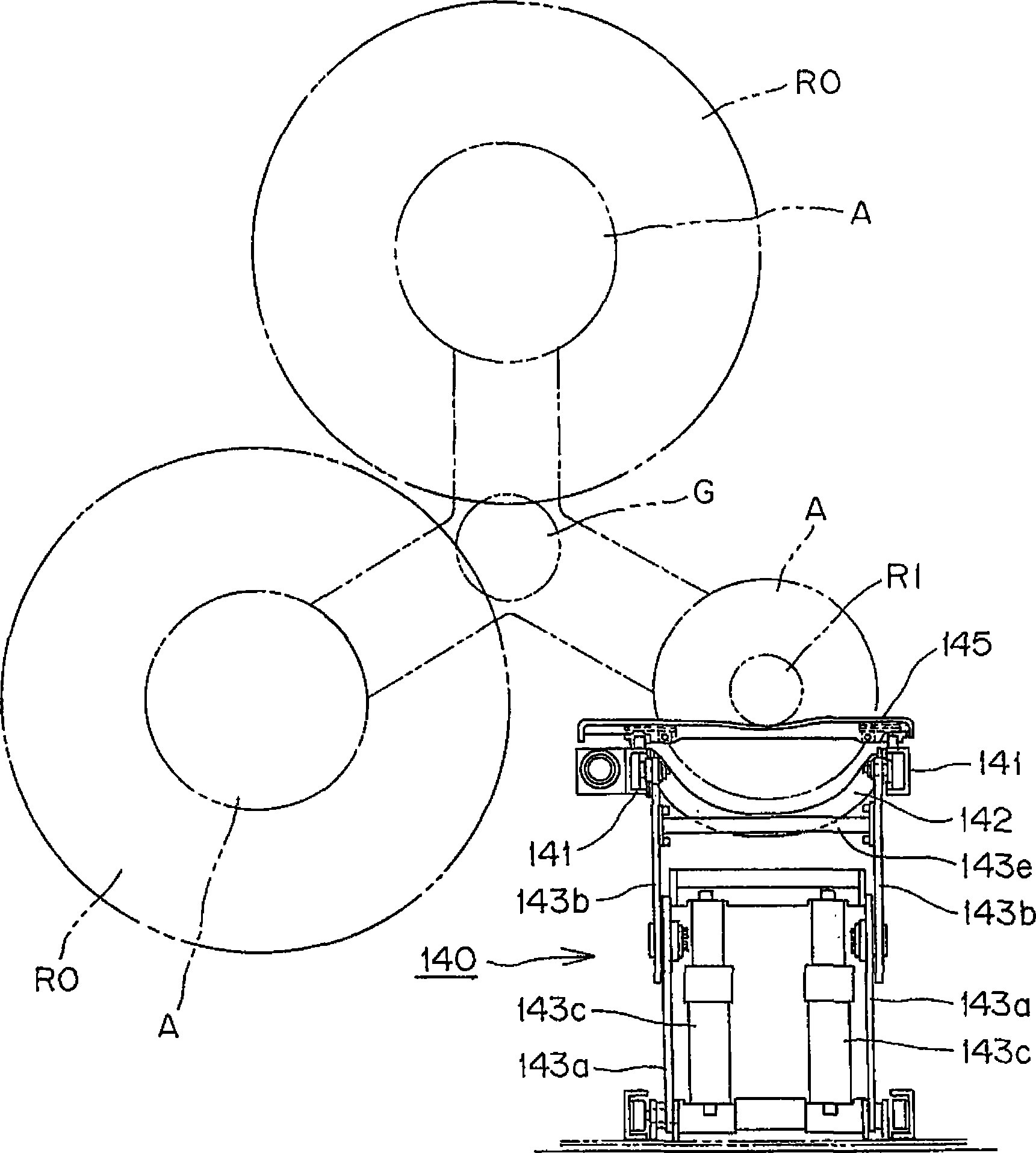
[0032] based on Figure 1 to Figure 6 An example of the present invention will be described. figure 1 It is an overall perspective view of the unmanned transport vehicle of the present invention. figure 2 is seen from the direction of arrow II figure 1 The side view of the relationship between the lifting unit of the unmanned conveyor vehicle and the paper feeding device of the rotary printing press shown, image 3 is seen from arrow III figure 1 The side view of the relationship between the lifting unit of the unmanned conveyor vehicle and the paper feeding device of the rotary printing press shown. in addition, Figure 4 It is a side view when the D-roll newspaper roll R1 in use is to be mounted on the paper feeding device of the rotary printing machine with the left end aligned by the unmanned transport vehicle of the present invention. Figure 5 It is a side view when the D-roll newspaper roll R1 in use has been left-aligned and mounted on the paper feeder of the ...


PUM


Abstract

An object of the invention is to provide an automated guided vehicle, which can be adapted to various types of rolls of newsprint such as narrow, medium and wide, irrespective of their diameters and in which low bedding, weight lightening and energy saving are obtained. The invention solves the above-mentioned problems by providing an automated guided vehicle comprising a traveling carriage, which supports a newsprint roll and automatically transports the supported roll between a storage station and a setting area in a rotary press machine. A hoisting / lowering unit is mounted on the travelingcarriage, which hoists and lowers the supported roll of newsprint in a vertiacal direction and installs and callbacks the newsprint roll. The invention is characterized in that the hoisting / lowering unit includes two spaced-apart hoisting / lowering frames provided in parallel to a traveling road surface, hoisting / lowering means, which hoisting / lowering raises and lowers the hoisting / lowering frames, an arc-shaped connecting member, which keeps a spacing between the two hoisting / lowering frames to avoid interference with the winding paper holding arms, linear guides respectively formed on uppersurfaces of said two hoisting / lowering frames and a moving table, bridging over said linear guide, slides along the guides.

Description

technical field [0001] The present invention relates to an unmanned newspaper roll transport vehicle for unmanned transport of newspaper rolls between a storage place and a place where a rotary printing machine is installed. An unmanned delivery vehicle for newspaper rolls with a lifting unit for installation and recovery. Background technique [0002] Conventionally, in a newspaper office or the like, an unmanned newspaper roll transport vehicle is generally used to supply new roll paper to a rotary printing machine or to collect a half-way newspaper roll. And, for newspaper rolls, newspaper rolls called A rolls with a length of 1626 mm, newspaper rolls called C rolls with a length of 1219 mm, and rolls called D rolls with a length of 813mm newspaper roll paper. [0003] Figure 7 It is a schematic side view showing a state in which an unused D roll of newspaper roll R2 is mounted on a rotary printing press in a conventionally used unmanned newspaper roll paper delivery v...

Claims


Application Information

Patent Timeline
Patent Type & Authority Applications(China)
IPC IPC(8): B66F9/06B66F7/00B65H19/12B65G54/02
CPCB66F9/063B65G43/08B65G43/02
Inventor 梅泽研二村田贵志
Owner TSUBAKIMOTO CHAIN CO
Why Eureka
Try Eureka