Method for designing swinging follower cylindrical cam contour line

A technology of cylindrical cam and design method, applied in the field of mechanical design, can solve problems such as inability to be practically applied, complex analytically, difficult to master, etc., and achieve the effect of simple design process, broad application prospects, and easy mastery

Inactive Publication Date: 2009-04-22
NINGBO INST OF TECH ZHEJIANG UNIV ZHEJIANG
View PDF1 Cites 17 Cited by
  • Summary
  • Abstract
  • Description
  • Claims
  • Application Information

AI Technical Summary

Problems solved by technology

[0005] The mathematical model established in literature [1] and the analytical formula of pressure angle derived from it have high precision, but because the analytical formula is too complicated and difficult to master, it cannot be practically applied at

Method used


Image

  • Method for designing swinging follower cylindrical cam contour line
  • Method for designing swinging follower cylindrical cam contour line
  • Method for designing swinging follower cylindrical cam contour line

Examples


Embodiment Construction

[0044] The present invention will be further described in detail below in conjunction with the accompanying drawings and specific examples, but the present invention is not limited to the following specific examples.

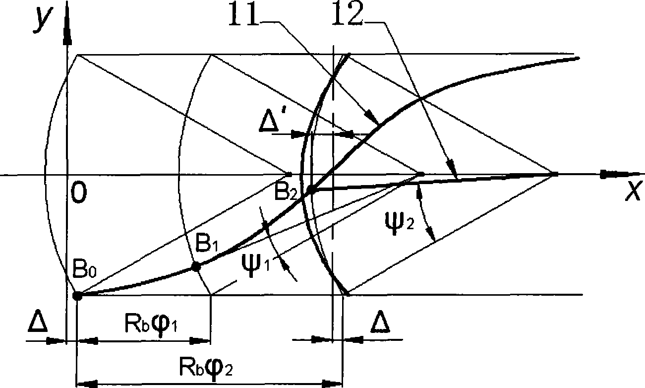
[0045] (1) Establish the curve equation of the contour expansion line

[0046] ① Introduce the coordinate expression of swinging from the 3D expansion of the moving part

[0047] That is to introduce the coordinate expression of the 3D development line of the displacement curve of the swing follower obtained in the applicant's previous patent "Processing Method of the Cylindrical Cam Groove of the Swing Follower" (Patent No.: ZL200610154488.9):

[0048]

[0049] In the formula: S is the displacement of the follower, the unit is mm; l is the length of the pendulum rod, the unit is mm; is the rotation angle of the cylindrical cam, in degrees (°); a is the distance from the swinging axis of the pendulum rod to the rotating axis of the cylindrical cam, in mm. ...


PUM


Abstract

The invention relates to a design method of a cylindrical cam profile of an oscillating follower. The method is characterized by comprising the following steps: introducing a coordinate expression of a 3D evolute of a displacement curve of the oscillating follower, putting forward a concept of a deviation angle, deducting the expression of the deviation angle according to a geometrical relation, and establishing a profile equation which is convenient for analyzing, designing and constructing the cylindrical cam of the oscillating follower; deducting an expression of a pressure angle according to the geometrical relation of the profile evolute, drawing a relation curve of a base radius R in relation to a maximum pressure angle alpha, and obtaining the minimum base radii which are corresponding to different allowable pressure angles; and programming an MATLAB program according to a known expression, namely, S=f(phi), 1, a and R, extracting coordinate values of the curve by MATLAB software after the operation of the program, pasting the coordinate values to AutoCAD software under a 'PLINE' command after processing, and then processing the coordinate values to 3D CAD software to obtain the profile. The solution process and the design process of the method are concise, visual, and easy to be controlled and practical, and have no design error.

Description

technical field [0001] The invention belongs to the field of mechanical design, and relates to a design method of a mechanical mechanism, in particular to a design method of a cylindrical cam profile of a swing follower. Background technique [0002] Many literatures have analyzed and researched the design of the cylindrical cam profile of the oscillating follower, such as [1] Wang Jingzhuo et al. Analytical method for the pressure angle of the conical cam mechanism of the oscillating follower with tapered rollers. Mechanical Design [J]. 2000.8 【2】Shi Yonggang, Wu Yangfang. Cam Mechanism Design and Application Innovation [M]. Beijing: Mechanical Industry Press, 2007. [0003] Wang Jingzhuo et al [1] analyzed and researched the tapered roller oscillating follower conical cam mechanism in detail, established a mathematical model of the conical cam mechanism based on the single parameter envelope surface theory, and deduced the The analytical formula of the pressure angle has ...

Claims


Application Information

Patent Timeline
IPC IPC(8): F16H53/00
Inventor 陈俊华
Owner NINGBO INST OF TECH ZHEJIANG UNIV ZHEJIANG
Why Eureka
Try Eureka