

Pneumatic loading type friction wear testing machine
A friction and wear test and loading mechanism technology, applied in the direction of testing wear resistance, etc., can solve the problems of expensive equipment, narrow test range, increase test cost, etc., and achieve convenient installation and use, wide adjustment range and low overall cost. Effect
- Summary
- Abstract
- Description
- Claims
- Application Information
AI Technical Summary
Problems solved by technology
Method used
Image

Examples
Embodiment 1
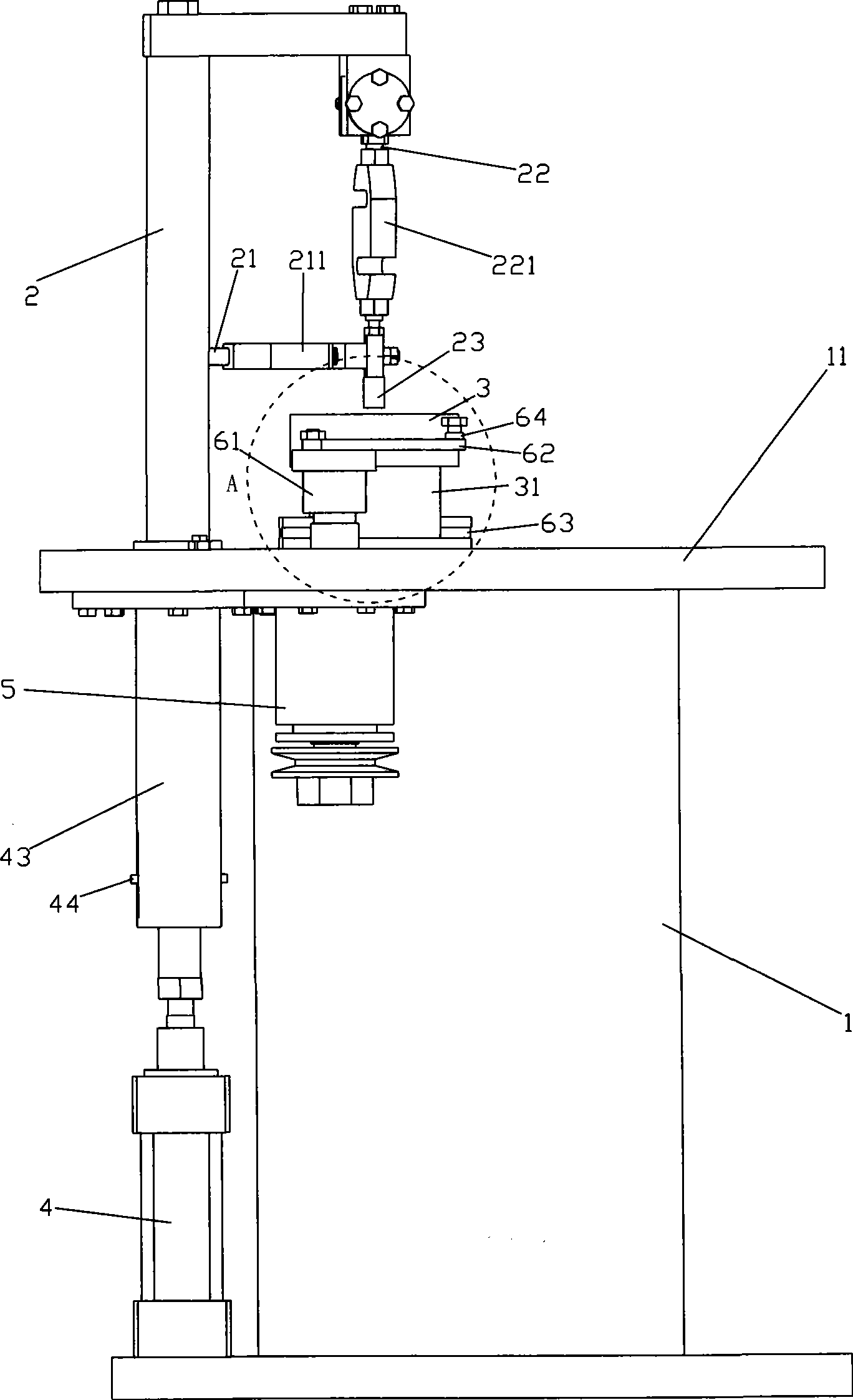
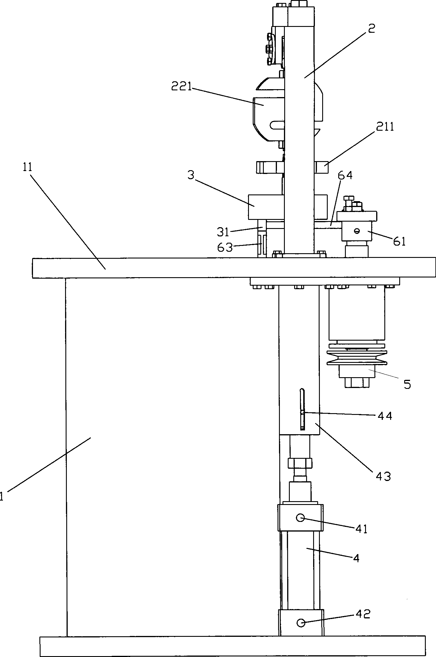
[0017] Such as figure 1 , 2 As shown in and 4, the pneumatic loading type friction and wear testing machine of the present invention includes a sample table 3, a loading mechanism, a reciprocating mechanism 6 and a frame 1, and an operating table 11 is arranged on the upper end of the frame 1, and a reciprocating mechanism is arranged on the operating table 11 6. There is a cylinder 4 arranged vertically on the base of the frame 1, and a guide sleeve 43 is provided on the lower surface of the console 11. The piston rod of the cylinder 4 is connected with the pressure head bracket 2 through the guide sleeve 43, and the pressure head bracket 2 It is an inverted L shape, and its vertical support rod is connected with the guide sleeve 43. A cantilever 22 extending vertically downward is arranged on the horizontal connecting rod, and a tension and pressure sensor 221 is arranged vertically on the cantilever 22. The tension and pressure sensor 221 is used to collect the loading loa...
Embodiment 2
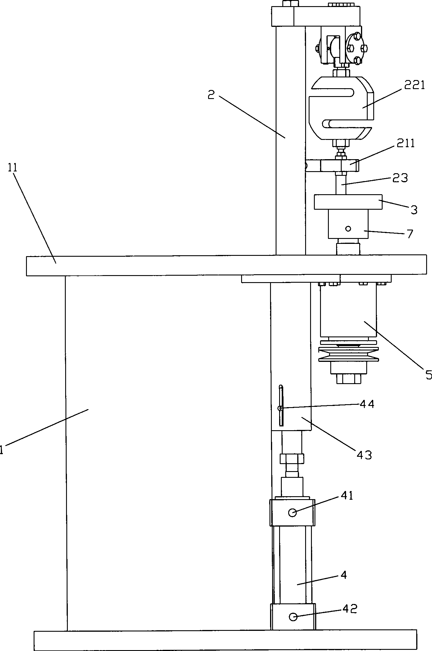
[0021] The device of the present invention can not only measure the friction behavior of the sample when reciprocating, but also measure the friction behavior of the sample when it rotates, such as image 3 As shown, the reciprocating mechanism is replaced by a rotating mechanism. The rotating mechanism includes a sample stage 3 and a sample stage base 7. The sample stage 3 is placed on the sample stage base 7, and the sample stage base 7 is fixed on the operation table 11. The sample stage base 7 There is a rotary output shaft arranged vertically, one end of the rotary output shaft is connected to the sample stage base 7, and the other end is connected to the driving motor power, so that the motor drives the sample stage 3 to rotate, and the friction behavior measurement during the rotary motion is realized. Other parts of the inventive device are the same as in Embodiment 1.
[0022] In the pneumatic loading type friction and wear testing machine of the present invention, th...
PUM
 Abstract
Description
Claims
Application Information