Dark field illumination objective lens apparatus

A technology for illuminating an objective lens and an illuminating device, applied in microscopes, optics, instruments, etc., can solve the problem of not taking into account the change of the focal length of the light source, and achieve the effect of improving inspection capabilities and improving work efficiency

Active Publication Date: 2009-04-22
南京东利来光电实业有限责任公司
View PDF4 Cites 14 Cited by
  • Summary
  • Abstract
  • Description
  • Claims
  • Application Information

AI Technical Summary

Problems solved by technology

Since the light source is set up in the microscope, the change of the focal length ...

Method used


Image

  • Dark field illumination objective lens apparatus
  • Dark field illumination objective lens apparatus
  • Dark field illumination objective lens apparatus

Examples


Embodiment approach 1

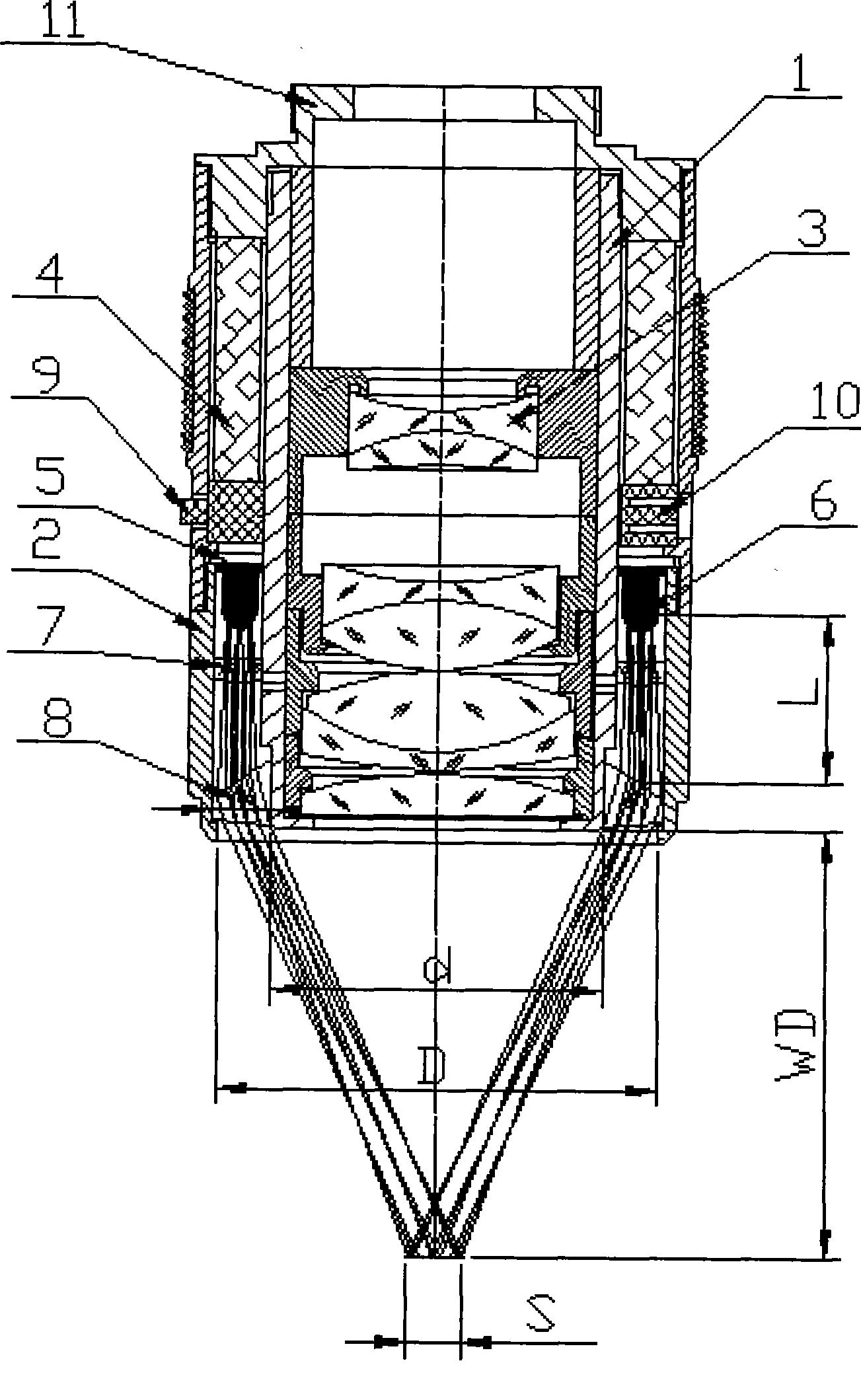
[0036] figure 1 It is a sectional view showing the dark field illumination objective lens device according to Embodiment 1 of the present invention.

[0037] This embodiment is composed of an inner cylinder 1 and an outer cylinder 2 whose axes coincide. A lens group 3 for imaging is installed in the inner cylinder 1 . The outer diameter of the inner cylinder 1 facing the observed object side is d (inner diameter of the ring), which is equivalent to the outer diameter of the bright field lens when the objective lens is used for bright field observation. The axis center of the outer cylinder 2 is the same as that of the inner cylinder 1 . There is an annular space between the outer cylinder 2 and the inner cylinder 1 . From top to bottom in the ring-shaped space, there are ring-shaped battery 4, substrate 5 for installing LED components, LED components 6, compensation lens 7 for improving the parallelism of LED emitted light, and converting the illumination light emitted by L...

Embodiment approach 2

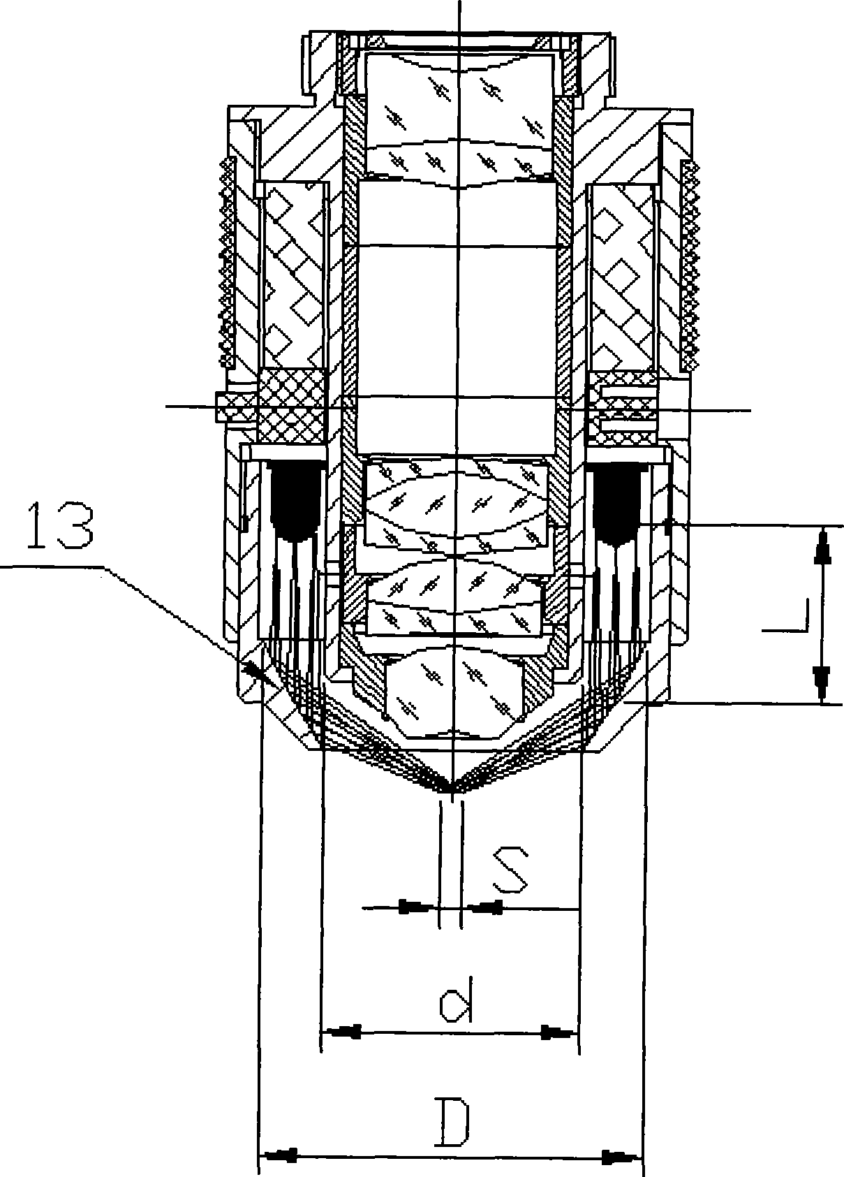
[0046] see image 3 A darkfield illumination objective arrangement employing an aspheric mirror 13 is shown. Except for the spherical reflector 13 , the rest of the structure is the same as that of Embodiment 1, so the description of the parts other than the aspheric reflector is omitted here.

[0047] In the second embodiment, the same as in the first embodiment, the illumination area S satisfies S≤(D-d), where D and d are the inner diameter of the outer cylinder and the outer diameter of the inner cylinder respectively (the outer diameter of the inner cylinder that clamps the imaging lens group ). In addition, the distance L between the LED element 6 and the aspheric reflector 13 preferably satisfies L>3.3(D-d).

[0048] The aspheric mirror 13 forms a tread and converts incident light into parallel light within the meridian plane. Therefore, the aspheric mirror 13 converts the illumination light emitted by the annularly arranged LED elements into parallel light in the sub...

Embodiment approach 3

[0050] Below, refer to Figure 4 An embodiment in which an objective lens device for dark field observation is realized by obliquely irradiating illumination light emitted by an LED element onto an illumination area S by using a ring-shaped tread lens will be described in detail.

[0051] Figure 4 It is a cross-sectional view of a dark field illumination objective lens device equipped with a tread lens 14 at the front end of the outer cylinder. In Embodiment 3, the installation method of the LED is different from Embodiments 1 and 2. In order to make the light emitted by the LED element obliquely irradiate the illumination area S without going through the optical axis bending, the front end of the outer tube 2 that accommodates the LED element The portion is in an open conical shape relative to the inner cylinder 1 . That is, the outer cylinder 2 extends from the middle of the inner cylinder 1 to the front end in an umbrella shape, and is used for mounting and fixing LED el...


PUM


Abstract

The invention relates to a dark view field object lens device which illumines the observed objects at the dark view field and used in a dark view field microscope utilizing the scattering and diffraction of the objects to observe. More particularly, the invention relates to a lighting and mounting structure of the dark view field object lens device. The object lens contains an inner cylinder and an outer cylinder. A combination of lenses used for imaging is installed inside the inner cylinder; an LED illuminating apparatus which is arranged in a ring shape and takes an LED original piece as light source is arranged at the outer side of the outer cylinder. In addition, an optical element which is arranged between the LED original piece and the observed objects transforms the light of LED in a meridian plane into parallel light and leads the parallel light to light the observed objects in an inclined way. The light emitted by the LED original piece is transformed into parallel light to light the observed objects in the meridian plane. After the image of the light scattered and diffracted by the observed objects is formed by an imaging object lens, the image is processed after being observed by using an eyepiece and shot by a camera. Screw thread is arranged at the periphery of the end part of the inner cylinder of the dark view field object lens device, so that the dark view field object lens device can be directly installed on a change over panel of a bright field microscopical. Therefore, the bright field microscopical can be directly switched for the observation of the dark view field.

Description

technical field [0001] The invention relates to a dark-field objective lens device used in a dark-field microscope that performs dark-field illumination on an observed object and observes by using scattered and diffracted light of the object. Background technique [0002] When inspecting integrated circuit (IC) patterns, scratches and dust on the surface of liquid crystal glass, it is more beneficial to use dark field illumination, so it is usually observed under dark field illumination. Different from the bright field illumination that irradiates the observed object along the optical axis, the dark field illumination projects the illumination light onto the observed object from the side and oblique direction, and the objective lens receives and observes the diffracted and scattered light of the observed object. [0003] The objective lenses used for dark field illumination recently have the following problems. In addition to the optical system of the microscope, another li...

Claims


Application Information

Patent Timeline
IPC IPC(8): G02B21/10G02B21/02
CPCG02B21/084
Inventor 赵跃东
Owner 南京东利来光电实业有限责任公司
Why Eureka
Try Eureka