Driving circuit apparatus

A driving circuit and driving voltage technology, applied in the direction of cathode ray tube indicators, instruments, static indicators, etc., can solve the problem of increasing the data line of the source driver

Inactive Publication Date: 2009-04-22
LAPIS SEMICON CO LTD
View PDF2 Cites 11 Cited by
  • Summary
  • Abstract
  • Description
  • Claims
  • Application Information

AI Technical Summary

Problems solved by technology

[0007] However, no matter in any method of implementing gamma correction analogly or digitally, if the image data is multi-bit (multi-gray scale), the source driver data lines need to be increased by a corresponding number.
Therefore, with the development of multi-channel source drivers in recent years, the increase in data lines has a great influence on the increase in chip size.

Method used


Image

  • Driving circuit apparatus
  • Driving circuit apparatus
  • Driving circuit apparatus

Examples


Embodiment Construction

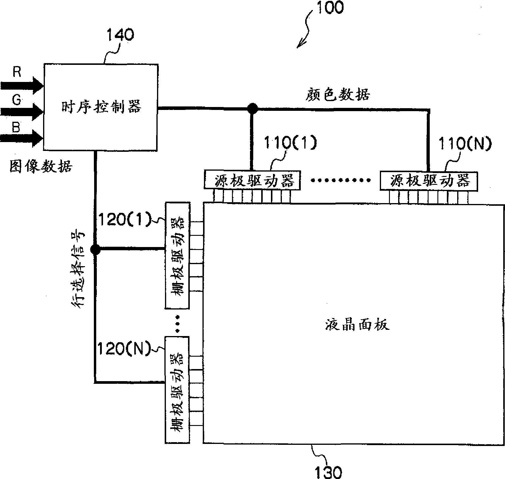
[0023] figure 1 A configuration diagram of the liquid crystal display 100 in the first embodiment of the present application is shown.

[0024] A liquid crystal display (hereinafter referred to as LCD) 100 includes a timing controller 140, source drivers 110(1)...110(N), gate drivers 120(1)...120(N), and a liquid crystal panel 130 (N is an integer of 1 or more). In addition, the source drivers 110 ( 1 ) . . . 110 (N) are simply referred to as the source driver 110 , and the gate drivers 120 ( 1 ) .

[0025] The timing controller 140 is respectively connected to the source drivers 110(1)...110(N) and the gate drivers 120(1)...120(N). In addition, the source drivers 110 ( 1 ) . . . 110 (N) and the gate drivers 120 ( 1 ) . . . 120 (N) are respectively connected to the liquid crystal panel 130 .

[0026] The display method of the LCD 100 is as follows. The timing controller 140 receives image data including RGB (Red-Green-Blue) signals output from an image processor, etc., and ...


PUM


Abstract

The present invention provides a driving circuit that reduces chip size of a source driver while maintaining image quality when image data is configured by multiple bits. The source driver provided in connection with a timing controller that converts image data into color data. The source driver displays an image by controlling pixel density of a liquid crystal panel. The source driver is divided into plural regions in units of pseudo linear elements to perform a gamma correcting operation based on a gamma characteristic. In the source driver a GMA voltage for each region is divided by resistive elements arranged between input signal lines. With respect to variation of plural divided GMA voltages, variation of the maximum high density region becomes coarser than variation of the maximum low density region in compliance with visual sensitivity of the density, a driving voltage is selected from a plurality of GMA voltages, and then the invention controls the pixel density of a liquid crystal panel based on the selected GMA voltage, and then transmits the images to the liquid panel.

Description

technical field [0001] The present invention relates to a driving circuit device, in particular to a driving circuit device for reducing the chip size of a source driver in a liquid crystal driving circuit. Background technique [0002] The display method of an ordinary liquid crystal display (hereinafter referred to as LCD (Liquid Crystal Display)) is as follows. The timing controller receives the image data output from the image processor, etc., sends a row selection signal to the gate driver, and outputs color data to the source driver. . The source driver resistively divides the GMA (Gamma: Gamma) voltage representing the voltage value of the gray scale of the color, and supplies the voltage corresponding to the color data to the liquid crystal panel, and in the row selected by the gate driver, from top to bottom Display the image below. At this time, due to the inherent gamma characteristics of the liquid crystal display, the display is performed on the liquid crystal...

Claims


Application Information

Patent Timeline
Patent Type & Authority Applications(China)
IPC IPC(8): G09G3/36G09G5/06
CPCG09G3/3685G09G2320/0285G09G3/3696G09G2320/0276
Inventor 木下宏之
Owner LAPIS SEMICON CO LTD
Why Eureka
Try Eureka