Passive microwave interception system

A microwave and power amplifier system technology, applied in the field of listening systems, can solve the problems of difficult debugging and tracking, difficult installation, narrow beam, etc., and achieve the effects of easy maintenance, high reliability and small size

Active Publication Date: 2009-04-22
南京国睿微波器件有限公司
View PDF0 Cites 5 Cited by
  • Summary
  • Abstract
  • Description
  • Claims
  • Application Information

AI Technical Summary

Problems solved by technology

Each method has its own limitations and disadvantages: the active wired method is difficult to install, requires maintenance (requires powe

Method used


Image

  • Passive microwave interception system
  • Passive microwave interception system
  • Passive microwave interception system

Examples


Embodiment Construction

[0012] The present invention will be described in further detail below with reference to the accompanying drawings and specific embodiments.

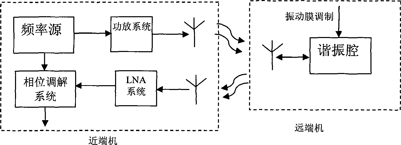
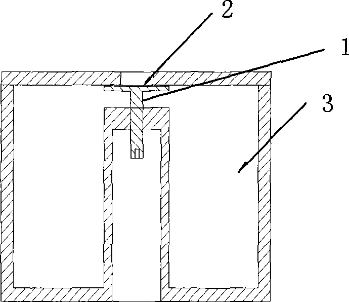
[0013] figure 1 , a passive microwave listening system, including a near-end machine and a far-end machine; the near-end machine includes a frequency source, a power amplifier system, an LNA system, and a modulation system, and the far-end machine includes a resonant cavity; the near-end machine frequency source produces a low-phase The noise point frequency signal is amplified by the power amplifier system and then transmitted by the near-end antenna; the far-end machine receives it through the far-end transceiver antenna and enters the resonant cavity and reflects back to the far-end transceiver antenna; the vibrating membrane feels the vibration of the outside air, causing the resonant cavity frequency The slight change of , which leads to the phase modulation of the reflected signal; the near-end receiving antenna receives the signa...


PUM


Abstract

The invention relates to a passive microwave interception system. The system comprises a local machine and a remote machine; the local machine comprises a frequency source, a power amplifier system, an LNA (Low Noise Amplifier) system and a modulation and demodulation system; the system is characterized in that the remote machine comprises a cavity resonator, the frequency source of the local machine produces low phase position noise spot frequency signals that are transmitted by a local antenna after amplification by the power amplifier system, the signals enters the cavity resonator after being received by a remote transceiving antenna of the remote machine and are reflected to the remote transceiving antenna, a vibration membrane feels the vibration of outside air to cause micro-change of resonant frequency of the cavity resonator and thereby result in the phase position modulation of reflected signals, the phase position is demodulated after the signals received by the local receiving antenna are amplified by the LNA system and audio modulating signals are demodulated by the modulation and demodulation system. The invention uses passive and wireless microwave interception system, thereby having very simple installation and maintenance, high reliability and good disguise; the remote machine without supply source is small in volume and easy to maintain.

Description

technical field [0001] The present invention relates to an interception system, in particular to a passive microwave interception system. Background technique [0002] At present, there are wired active methods, or lasers, etc., for remote monitoring methods. Each method has its own limitations and disadvantages: Active wired methods are difficult to install, require maintenance (requires power), and are more difficult to conceal. Due to the high frequency of the laser, the beam is too narrow, and it is difficult to debug and track. SUMMARY OF THE INVENTION [0003] 1. Technical problems to be solved: [0004] In view of the above-mentioned problems, the present invention provides a passive microwave interception system that is concealed, convenient and easy to maintain. [0005] 2. Technical solutions: [0006] The present invention includes a near-end machine and a far-end machine; the near-end machine includes a frequency source, a power amplifier system, an LNA sys...

Claims


Application Information

Patent Timeline
IPC IPC(8): H04B1/00
Inventor 方汉平
Owner 南京国睿微波器件有限公司
Why Eureka
Try Eureka