Electric impulse auxiliary superplastic forming device and method

A technology of superplastic forming and electric pulse, applied in the direction of forming tools, metal processing equipment, manufacturing tools, etc., can solve the problems of high energy consumption, low energy utilization rate, long heating time and other problems of superplastic inflatable forming process, to avoid Effects of heat loss, reduced deformation resistance, and uniform temperature distribution

Inactive Publication Date: 2009-04-29
HARBIN INST OF TECH
View PDF0 Cites 26 Cited by
  • Summary
  • Abstract
  • Description
  • Claims
  • Application Information

AI Technical Summary

Problems solved by technology

[0006] In order to solve the shortcomings of high energy consumption and low efficiency in the traditional superplastic inflatable forming process caused b

Method used


Image

  • Electric impulse auxiliary superplastic forming device and method

Examples


specific Embodiment approach 1

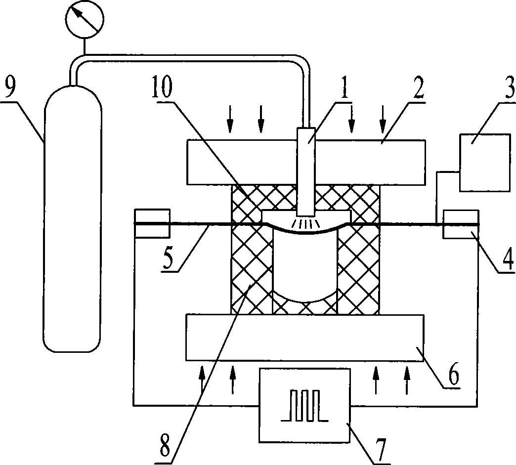
[0013] Specific implementation mode one: combine figure 1 Describe this embodiment, the device of this embodiment is made up of high-frequency pulse power supply 7, air pressure device, insulating mold, indenter and blank clamping electrode; 8 are respectively placed on the upper and lower sides of the blank 5 to be formed, the forming part of the blank 5 to be formed is placed in the cavity of the upper mold 10 and the lower mold 8, and the blank 5 to be formed separates the upper mold 10 and the lower mold 8 into two Cavity, the outer edge of the blank 5 to be formed is placed outside the insulation mold, the pressure head is closed and pressed against the insulation mold and the blank 5 to be formed, the air outlet of the air pressure device penetrates the pressure head and the upper part of the insulation mold and is placed in the cavity of the insulation mold The two chucks 4 of the blank clamping electrode clamp the outer edge of the blank 5 to be formed, and the electro...

specific Embodiment approach 2

[0014] Specific implementation mode two: combination figure 1 Describe this embodiment, the difference between this embodiment and the specific embodiment is that an infrared thermometer 3 is added, and the probe of the infrared thermometer 3 is arranged on the blank 5 to be formed, and the blank to be formed is measured in real time by the infrared thermometer 3 5 temperature. Other compositions and connection methods are the same as those in Embodiment 1.

specific Embodiment approach 3

[0015] Specific implementation mode three: combination figure 1 Describe this embodiment, the difference between this embodiment and specific embodiment 1 or 2 is that the insulating mold is made of ceramic material, and the insulating ceramic mold will not divert the current flowing through the blank 5 to be formed, reducing energy loss. Other compositions and connection modes are the same as those in Embodiment 1 or 2.


PUM


Abstract

The invention discloses a superplastic forming device with auxiliary of electrical pulse and a method thereof, which relate to the technical field of superplastic air bulking forming and solve the defect of low energy utilization. An upper mould and a lower mould of the device are respectively positioned at the upper side and the lower side of the blank to be formed, a forming part is placed inside a cavity of the mould, a pressure head tightly presses an insulation mould and the blank to be formed in a way of sealing, an air outlet of an air pressure device penetrates the pressure head and the insulation mould and is arranged inside the cavity; and a high frequency pulse power source, a blank holding electrode and the blank to be formed form an electrifying loop. The steps for applying the device are as follows: firstly, according to the cross sectional dimension of the blank to be formed and resistance data, a current parameter is chosen so as to lead the blank to be formed to be heated to the superplastic forming temperature, and the heating speed can be up to 50-100 DEG C per second; secondly, the edge-pressing force of a press ram is regulated, inert gas is introduced into the cavity by the pressure device so as to lead the blank to occur superplastic deformation. Applied in the complex parts manufacturing industry, the invention greatly improves the utilization of the manufacturing energy and the efficiency of heating.

Description

technical field [0001] The invention relates to the technical field of superplastic inflation forming, in particular to an electric pulse assisted superplastic forming device and method. Background technique [0002] As an advanced material forming technology, superplastic inflatable forming technology has the advantages of small forming pressure, good quality of formed parts, stable size, and one-time precision forming. It is very suitable for processing complex parts that are difficult to process by ordinary methods. , construction, transportation, electronics and other aspects have been more and more widely used. It is recorded in the current situation and development of material superplasticity research written by Ding Hua et al. on pages 1059 to 1067 of the Chinese Journal of Nonferrous Metals on April 7, 2004. The general process of superplastic inflation forming is as follows: first, heat the superplastic plate evenly, and keep its temperature within the range of its...

Claims


Application Information

Patent Timeline
IPC IPC(8): B21D26/02B21D37/16B21D37/01
Inventor 张凯锋李超
Owner HARBIN INST OF TECH
Why Eureka
Try Eureka