
Drill end actuator

A technology of end effector and optical axis, which is applied in the direction of drilling/drilling equipment, parts of boring machine/drilling machine, metal processing equipment, etc., and can solve problems such as difficulty in ensuring consistency in accuracy and quality, boring process, and heavy workload. , to achieve the effect of optimizing tool structure and cutting parameters, compact overall structure and good rigidity

Inactive Publication Date: 2009-04-29
BEIHANG UNIV
View PDF0 Cites 32 Cited by
  • Summary
  • Abstract
  • Description
  • Claims
  • Application Information

AI Technical Summary

Problems solved by technology

Traditional manual drilling involves heavy workload, boring process, low drilling efficiency, difficulty in ensuring consistency of hole accuracy and quality, and high manpower and material costs for mass production.

Method used


Image

  • Drill end actuator
  • Drill end actuator
  • Drill end actuator

Examples


Embodiment Construction

[0023] The present invention will be further described in detail below in conjunction with the accompanying drawings.

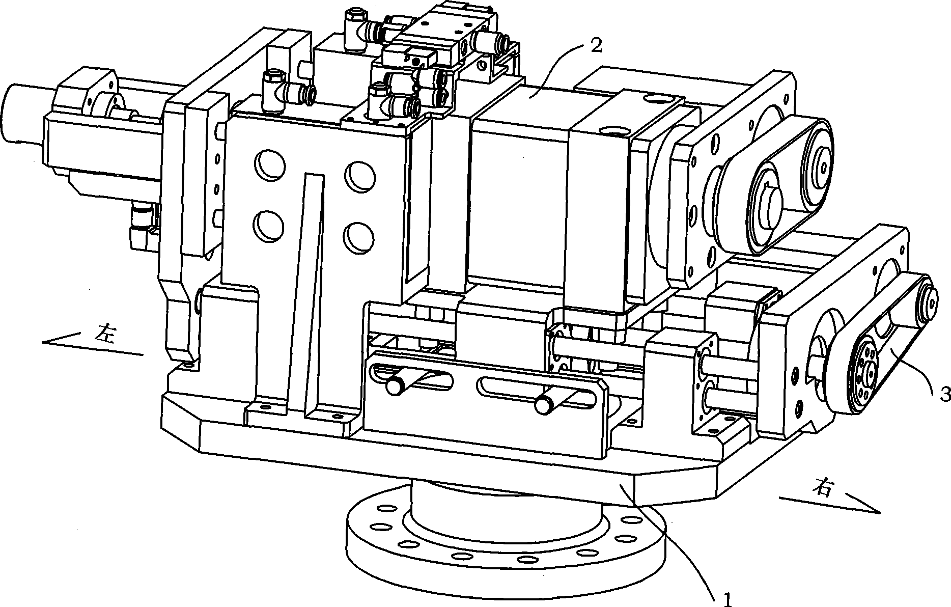
[0024] see figure 1 As shown, a drilling end effector for an industrial robot of the present invention includes a support unit 1, a spindle unit 2 and a feed unit 3; the rear plate 305 of the feed unit 3 is connected with The four optical axes (A optical axis 121 , B optical axis 122 , C optical axis 123 , and D optical axis 124 ) of the support unit 1 and the spindle unit 2 are installed on the spindle head support 102 of the support unit 1 .

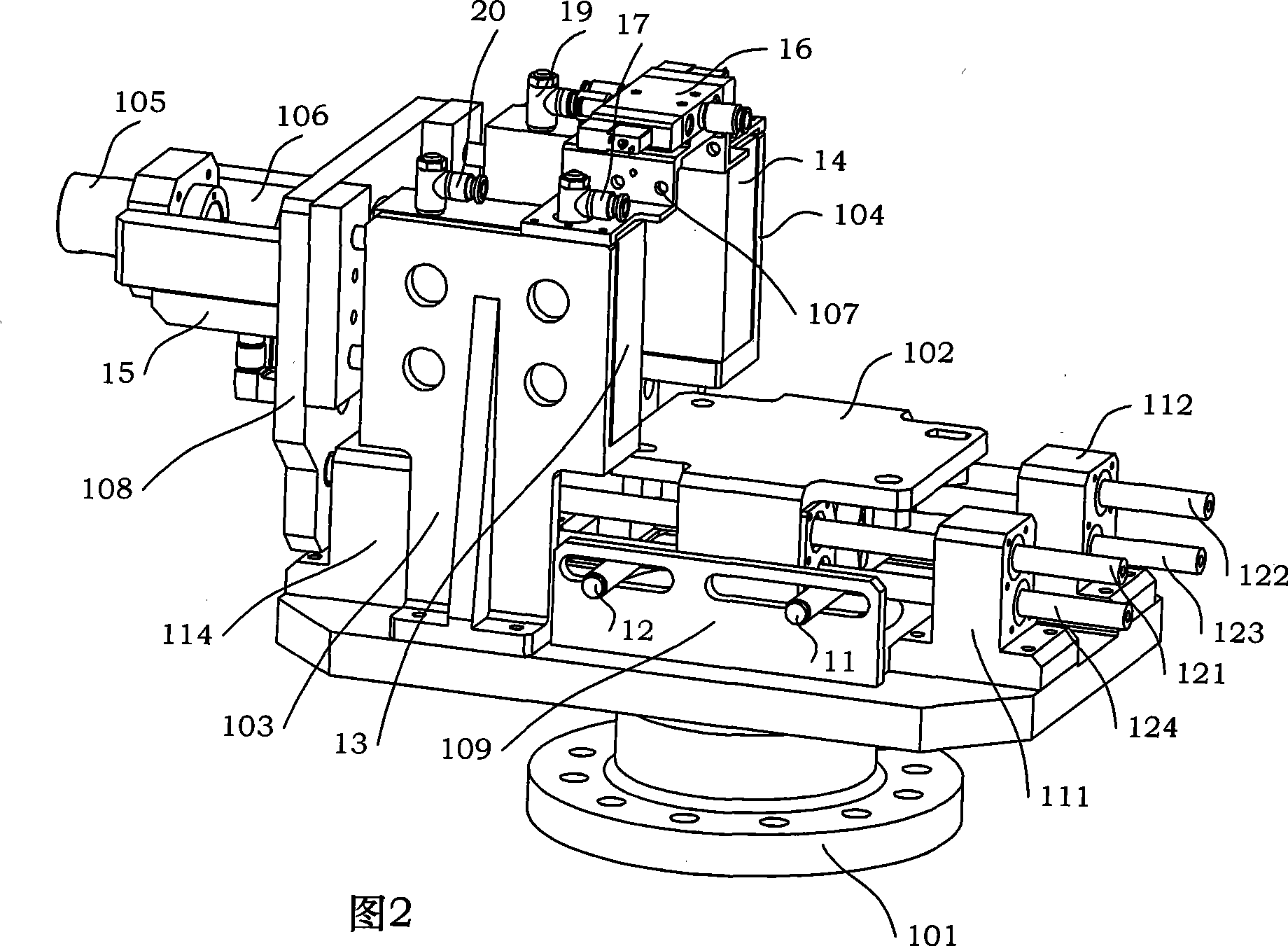
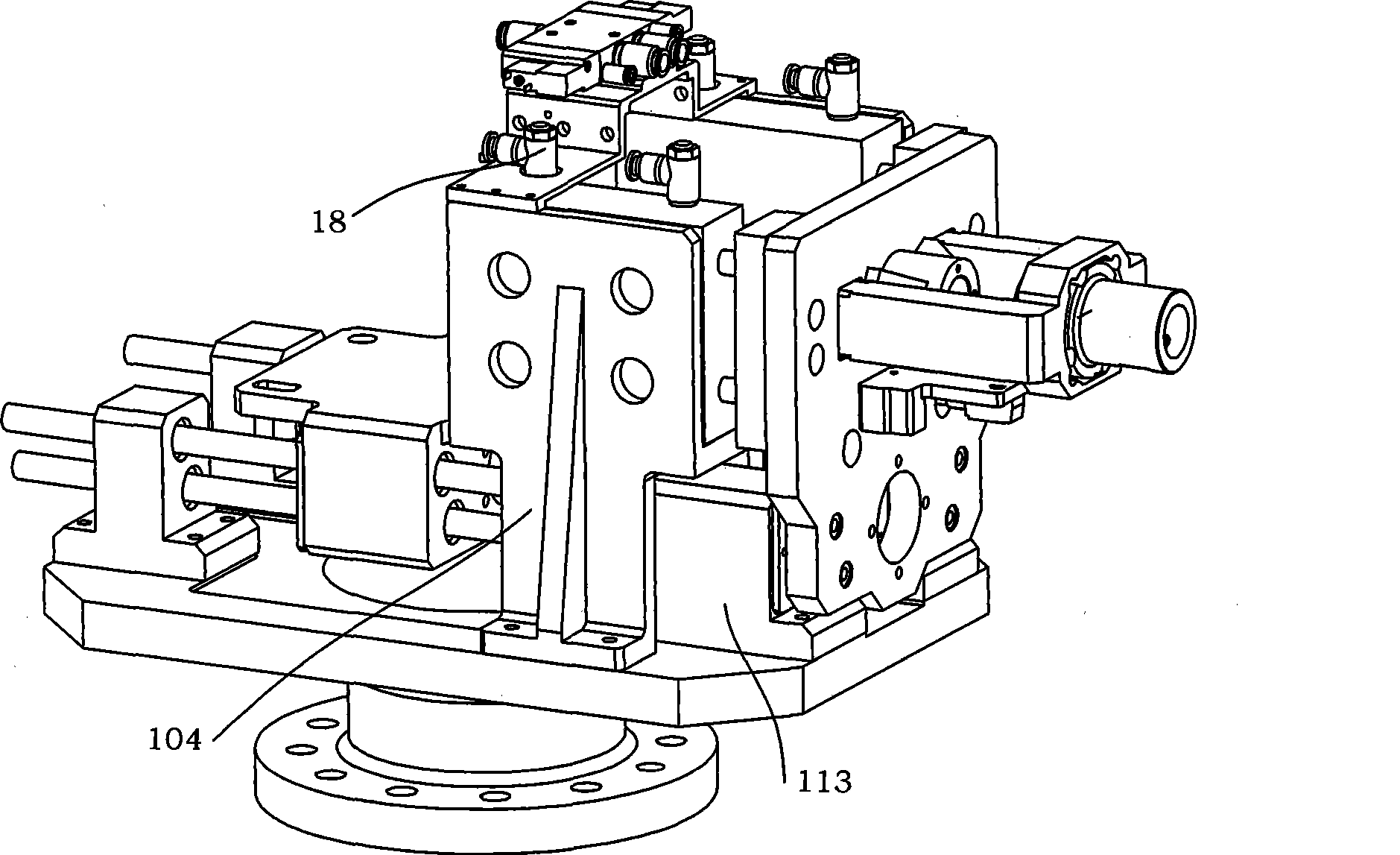
[0025] See Figure 2, Figure 2A , as shown in Figure 2B, the support unit 1 includes a base 101, four shaft seats (A shaft seat 111, B shaft seat 112, C shaft seat 113, D shaft seat 114), four optical axes (A optical axis 121 , B optical axis 122, C optical axis 123, D optical axis 124), two cylinder supports (A cylinder support 103, B cylinder support 104), spindle head support 102, A connecting plate 107, front pl...


PUM


Abstract

The invention discloses a drilling terminal end actuator used for industrial robots, comprising a spindle unit, a feed unit and a supporting unit. The spindle unit comprises a precise spindle head, a spindle motor and drive, an ER spring collet, a tool holder, a tool, a synchronous belt and a pulley; the feed unit comprises a linear ball bearing guide bushing and a special axis, a screw pair, a feed motor and drive, the synchronous belt and the pulley; and the supporting unit comprises a pedestal, a shaft seat, a precise spindle head support, a cylinder support, a pressure head pipe shell, a presser foot, a front plate, a rear plate, an electromagnetic valve connecting plate, a spindle motor connecting plate and a limit switch connecting plate. The spindle unit realizes the adjustable cutting speed of the drill, the feed unit realizes the adjustable feed speed and feed travel of the drill, and the supporting unit ensures the whole stiffness of the terminal end actuator. The drilling terminal end actuator can constitute a flexible drilling and cutting system by being combined with the robot for use, which can improve the drilling efficiency and accuracy, improve the drilling quality and reduce the labor duplication of workers.

Description

technical field [0001] The invention relates to the field of robot drilling, more particularly, to a drilling end effector suitable for industrial robots. Background technique [0002] Hole processing plays an important role in aviation manufacturing. It has been reported in the literature that about 40 million holes are drilled and processed each year on an assembly line of a wing. Traditional manual drilling involves heavy workload, boring process, low drilling efficiency, difficulty in ensuring consistency in hole accuracy and quality, and high manpower and material costs for mass production. With the improvement of the robot's position accuracy, load capacity and the development of position and stiffness compensation technology, the robot can be used as an efficient mobile platform, and combined with the drilling end effector, a flexible drilling system can be formed, which improves productivity and It embodies the concept of lean system. The end effector is a key part...

Claims


Application Information

Patent Timeline
Patent Type & Authority Applications(China)
IPC IPC(8): B23B47/00B23B47/26B23B47/20
Inventor 毕树生梁杰宗光华战强
Owner BEIHANG UNIV
Learn More