Helical feeder

A technology of screw feeding and screw blades, which is applied in the field of screw feeders, can solve problems affecting production speed and production efficiency, increasing production costs, affecting the appearance or quality of finished products, and achieving high production efficiency, good sealing, and small footprint effect

Inactive Publication Date: 2009-04-29
SHENGLI OIL FIELD SHENGLI POWER MACHINERY GRP
View PDF0 Cites 8 Cited by
  • Summary
  • Abstract
  • Description
  • Claims
  • Application Information

AI Technical Summary

Problems solved by technology

[0002] At present, the commonly used screw feeder in the industry is composed of a frame, a screw feeder and a vibrating motor. When the feed inlet enters the pellets, the material is lifted by the vibration of the vibrating motor. The screw feeder with this structure , there are mainly the following defects: when the pellets are in production, a lot of powder or small particles will be produced due to many reasons, which will affect the appearance or quality of the finished product. In order to remove the powder or small particles, secondary processing such as wind blowing is required. Screening, cleaning, etc., seriously affect the production speed and production efficiency, and increase production costs

Method used


Image

  • Helical feeder

Examples


Embodiment Construction

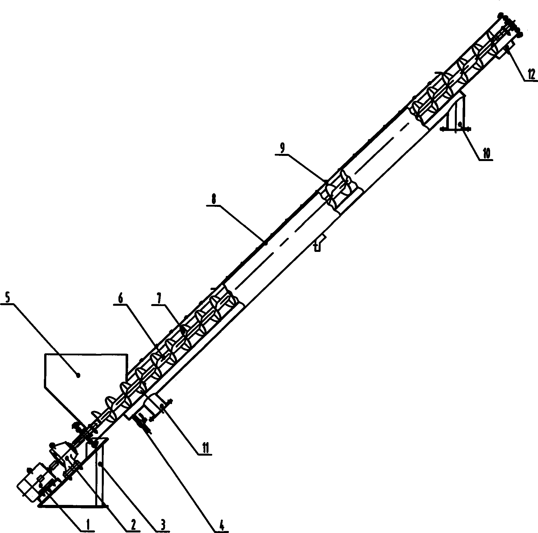
[0011] Referring to the drawings, a screw feeder includes a motor 1 , a reducer 2 , a motor frame 3 , a drain valve 4 , a screw feed shaft 6 , a screw blade 7 , a material channel and a casing 8 . The motor 1 is connected to the reducer 2 and the screw feeding shaft 6 in sequence. The screw feeding shaft 6 is installed in the material channel and the casing 8, and the screw feeding shaft 6 is provided with a spiral blade 7 along the axis. The material inlet 5 is installed on the upper part of the lower end of the material channel and the casing 8, the drain valve 4 and the gas outlet 11 are installed at the lower part, the observation port 9 is installed in the middle section of the material channel and the outer casing 8, and the gas inlet 10 and the material outlet 12 are installed at the upper end. A material inlet 12 is installed at the lower part, a motor frame 3 is installed under the material inlet 12 , and a motor 1 and a reducer 2 are installed on the motor frame 3 . ...


PUM


Abstract

The invention relates to a spiral feeder, which comprises a motor, a decelerator, a motor frame, a liquor drainage valve, a spiral feeding shaft, spiral blades, a material channel and a shell and is characterized in that the motor is connected with the decelerator and the spiral feeding shaft in sequence, and the spiral feeding shaft is arranged in the material channel and the shell and is provided with the spiral blades along the axial line, and the upper part of the material channel and the lower end of the external shell is provided with a material inlet while the lower part is provided with the liquor drainage valve and a gas outlet, and the middle section of the material channel and the shell is provided with viewing ports while the upper end is provided with a gas inlet and a material outlet and the lower part is provided with the material inlet, and the motor frame is arranged under the material inlet and is provided with the motor and the decelerator. The spiral feeder with functions of speed controlling and preheating is characterized by small volume, high efficiency, good sealing, safe and convenient operation and low cost, and can be widely applied in the lifting and delivering work of materials.

Description

1. Technical field [0001] The invention relates to a rotary piston type machine, in particular to a screw feeder. 2. Background technology [0002] At present, the commonly used screw feeder in the industry is composed of a frame, a screw feeding tray and a vibration motor. When the feed port enters the pellets, the material is lifted by the vibration of the vibration motor. The screw feeder of this structure , there are mainly the following defects: when the pellets are in production, a lot of powder or small particles will be produced for many reasons, which will affect the appearance or quality of the finished product. Screening, cleaning, etc., seriously affect the production speed and production efficiency, and increase production costs. 3. Content of the Invention [0003] The purpose of the present invention is to provide an improved screw feeder, which adopts a semi-closed material channel that can preheat the material and a cycloid reducer to control the material...

Claims


Application Information

Patent Timeline
Patent Type & Authority Applications(China)
IPC IPC(8): B65G33/26B65G33/08B65G33/24
Inventor 陈宜亮祝传艮李德良任淑琼刘瑞刚
Owner SHENGLI OIL FIELD SHENGLI POWER MACHINERY GRP
Why Eureka
Try Eureka